


13
I
I
n
n
s
s
t
t
a
a
l
l
l
l
i
i
n
n
g
g
t
t
h
h
e
e
P
P
o
o
r
r
t
t
c
c
o
o
n
n
t
t
.
.
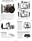
TToo RReemmoovvee PPoorrtt
To remove the port lift up on each Release Button and slide the
port lock away from the port.
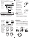
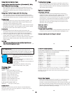
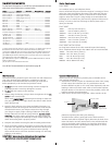
PPoorrtt SSeeaall IInnssiiddee VViieeww
If the port is installed before the
camera is inserted into the housing,
look on the inside of the housings at
the port seal. Check to see that the
o’ring is properly sealed as shown in
figure 1 and not extruded as shown
in figure 2.
Fig. 1
Fig. 2
C
C
a
a
u
u
t
t
i
i
o
o
n
n
:
:
After installing the port, turn the Zoom Control knob on the
housing. If the Zoom Control is difficult to turn, the gear sleeve
may be warped. If so reduce or omit any rubber installed on the
Zoom Clamp. (Fig.H on pg.11).
If the Zoom Clamp is still warped,
use of the #5509.28 package may be required. (See page 7)
15
UUssiinngg tthhee CCoonnvveerrssiioonn CCiirrccuuiittrryy
((SSeett DDSS SSuubbssttrroobbee ttoo TTTTLL mmooddee))
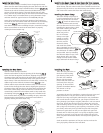
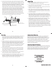
•• MMooddee aanndd CCoommppeennssaattiioonn DDiiaall
Note that the TTL
compensation values
are located in the
yellow band. Manual
compensation values
are located in the
black band. Rotate
the Dial to switch
between TTL and
Manual Modes.
•• TTTTLL MMooddee
TTL Mode
compensation values
are indicated in the
yellow band. Place
the Setting Indicator to
TTTTLL ffoorr NNOO CCoommppeennssaattiioonn
. Rotate the
Dial either direction to select +/- compensation. Place the Setting
Indicator to the desired compensation value. Note that in TTL
compensation values are in 1/3 f-stops.
•• MMaannuuaall MMooddee
Manual Mode compensation values are indicated in the black
band. Rotate the Dial to place the Setting Indicator to the desired
compensation value. Note that in Manual Mode compensation
values are in 1/2 f-stops from (F) full power to -3 f-stops.
((SSeett DDSS
SSuubbssttrroobbee ttoo TTTTLL mmooddee))
UUssiinngg EExxtteerrnnaall SSttrroobbeess CCoonntt..
DIAL
TTL Scale
(yellow)
(1/3 stops)
Manual Scale
(black)
(1/2 stops)
Setting
Indicator
14
U
U
s
s
i
i
n
n
g
g
E
E
x
x
t
t
e
e
r
r
n
n
a
a
l
l
S
S
t
t
r
r
o
o
b
b
e
e
s
s
This housing has Conversion Circuitry built into the housing.
W
hen used with Ikelite DS Substrobes the Conversion Circuitry
provides real Nikon iTTL flash exposure with over and under-
exposure compensation from +1 1/3 to - 1 1/3 f-stops in 1/3 stop
increments.
NNOOTTEE:: FFllaasshh EExxppoossuurree CCoommppeennssaattiioonn sseett iinn tthhee ccaammeerraa wwiillll bbee
aaddddeedd oorr ssuubbttrraacctteedd ffrroomm tthhee ccoommppeennssaattiioonn sseett oonn tthhee
h
h
o
o
u
u
s
s
i
i
n
n
g
g
c
c
o
o
n
n
v
v
e
e
r
r
s
s
i
i
o
o
n
n
c
c
i
i
r
r
c
c
u
u
i
i
t
t
r
r
y
y
i
i
n
n
i
i
T
T
T
T
L
L
.
.
NNOOTTEE:: BBaallaanncceedd FFiillll FFllaasshh ccaannnnoott bbee uusseedd..
DDoo nnoott uussee rreedd--eeyyee rreedduuccttiioonn sseettttiinngg..
NNoottee:: WWhheenn UUssiinngg aa DDSS--220000 SSuubbssttrroobbee
IInn CCuussttoomm SSeettttiinngg EE11:: ffllaasshh ssyynncc ssppeeeedd sseettttiinngg uussee aa sshhuutttteerr
ssppeeeedd ooff 11//112255 ooff aa sseeccoonndd oorr sslloowweerr..
The Conversion Circuitry also offers Manual exposure control
with 3 1/2 f-stops of under-exposure control in 1/2 stop
increments.
The Conversion Circuitry is powered by the Ikelite DS Substrobe
when connected to the housing with the #4103.51 single or
#4103.52 dual sync cord.
See page 12 for DS Substrobe compatibility with the Conversion
Circuitry.
16
NNOOTTEE:: DDSS SSuubbssttrroobbee UUpp--ddaattee mmaayy bbee rreeqquuiirreedd..
DDSS5500 SSuubbssttrroobbeess
• DS50 SubStrobes with a Serial Number below 63,850 can not be
updated to operate with the Conversion Circuitry.
• DS50 SubStrobes with a Serial Number between 63,850 and
69,999 operate with the Conversion Circuitry, but require update
to provide optimum performance.
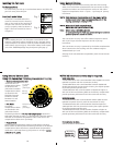
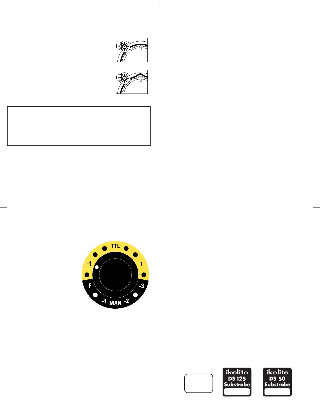
• DS50 Substrobe with a Serial Number of 70,000 or higher or
with one of the two following labels in the battery compartment
provide optimum performance with the Conversion Circuitry.
DDSS112255 SSuubbssttrroobbeess
• DS125 Substrobes with a Serial Number below 2,500 must be
updated to operate correctly with the Conversion Circuitry.
• DS125 Substrobes with a Serial Number between 2,501 and
4,900 operate with the Conversion Circuitry but require update
to provide optimum performance.
• DS125 Substrobe with a Serial Number of 5,000 or higher or
with one of the two following labels in the battery compartment
provide optimum performance with the Conversion Circuitry.
ikelite
SubstrobeSubstrobe
MOD-NC
serial number
serial number
FFoorr SSuubbssttrroobbee UUpp--DDaattee::
Contact Ikelite for information.