


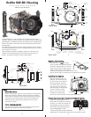
9
I
I
n
n
s
s
t
t
a
a
l
l
l
l
i
i
n
n
g
g
t
t
h
h
e
e
P
P
o
o
r
r
t
t
c
c
o
o
n
n
t
t
.
.
To prepare the port for installation, remove the port o-ring
a
nd lightly lubricate it. The port seal is a side-to-side seal and
requires the o-ring to be lightly lubricated for easy installation.
Put a small amount of lubricant on your fingers and draw the
o-ring through your fingers to lightly lubricate it. Do not
s
tretch the o-ring. Check that the lip of the port where the
o-ring fits and the sealing surface on the housing are clean.
Place the port, with o-ring into the housing’s port opening.
Press the port firmly and evenly into the port opening while
slightly rotating the port until you feel the port slide into place.
Continue to push down on the port and push each port lock
forward until it clicks into place. It may help to slightly rotate
the port as you push in on the port lock. When the port lock
clicks into place the Release Button will drop down against
the port lock.
Check around the perimeter of the port seal to see that the
o-ring is properly sealed and not extruded.
TToo RReemmoovvee PPoorrtt
To remove the port lift up on each Release Button and slide
the port lock away from the port.
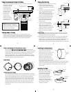
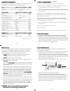
PPoorrtt SSeeaall IInnssiiddee VViieeww
If the port is installed before the camera
is inserted into the housing, look on the
inside of the housings at the port seal.
Check to see that the o-ring is properly
sealed as shown in figure 1 and not
extruded as shown in figure 2.
10
U
U
s
s
i
i
n
n
g
g
E
E
x
x
t
t
e
e
r
r
n
n
a
a
l
l
S
S
t
t
r
r
o
o
b
b
e
e
s
s
This housing has Conversion Circuitry built into the housing.
W
hen used with Ikelite DS Substrobes the Conversion Circuitry
provides real Sony TTL flash exposure with over and under-
exposure compensation from +1 1/3 to - 1 1/3 f-stops in 1/3 stop
increments.
NNoottee:: FFllaasshh EExxppoossuurree CCoommppeennssaattiioonn sseett iinn tthhee ccaammeerraa wwiillll bbee
aaddddeedd oorr ssuubbttrraacctteedd ffrroomm tthhee ccoommppeennssaattiioonn sseett oonn tthhee
h
h
o
o
u
u
s
s
i
i
n
n
g
g
c
c
o
o
n
n
v
v
e
e
r
r
s
s
i
i
o
o
n
n
c
c
i
i
r
r
c
c
u
u
i
i
t
t
r
r
y
y
i
i
n
n
T
T
T
T
L
L
.
.
The Conversion Circuitry also offers Manual exposure control
with 3 1/2 f-stops of under-exposure control in 1/2 stop
increments.
The Conversion Circuitry is powered by the Ikelite DS Substrobe
when connected to the housing with the #4103.51 single or
#4103.52 dual sync cord.
NNoottee::
See page 12 for DS Substrobe compatibility with the Conversion
Circuitry.
11
UUssiinngg EExxtteerrnnaall SSttrroobbeess CCoonntt..
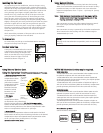
UUssiinngg tthhee CCoonnvveerrssiioonn CCiirrccuuiittrryy
((SSeett DDSS SSuubbssttrroobbee ttoo TTTTLL mmooddee))
•• MMooddee aanndd CCoommppeennssaattiioonn DDiiaall
Note that the TTL
compensation values
are located in the
yellow band. Manual
compensation values
are located in the
black band. Rotate
the Dial to switch
between TTL and
Manual Modes.
•• TTTTLL MMooddee
TTL Mode
compensation values
are indicated in the yellow band.
Place the Setting Indicator to
TTTTLL ffoorr NNOO CCoommppeennssaattiioonn
.
Rotate the Dial either direction to select +/- compensation.
Place the Setting Indicator to the desired compensation value.
Note TTL compensation values are in 1/3 f-stops.
•• MMaannuuaall MMooddee
Manual Mode compensation values are indicated in the black
band. Rotate the Dial to place the Setting Indicator to the desired
compensation value. Note Manual Mode compensation values
are in 1/2 f-stops from (F) full power to -3 f-stops.
((SSeett DDSS SSuubbssttrroobbee ttoo TTTTLL mmooddee))
DIAL
TTL Scale
(yellow)
(1/3 stops)
Manual Scale
(black)
(1/2 stops)
Setting
Indicator
12
NNOOTTEE:: DDSS SSuubbssttrroobbee UUpp--ddaattee mmaayy bbee rreeqquuiirreedd..
DDSS5500 SSuubbssttrroobbeess
• DS50 SubStrobes with a Serial Number below 63,850 can not
be updated to operate with the Conversion Circuitry.
• DS50 SubStrobes with a Serial Number between 63,850 and
69,999 operate with the Conversion Circuitry, but require update
to provide optimum performance.
• DS50 Substrobe with a Serial Number of 70,000 or higher or
with one of the two following labels in the battery compartment
provide optimum performance with the Conversion Circuitry.
DDSS112255 SSuubbssttrroobbeess
• DS125 Substrobes with a Serial Number below 2,500 must be
updated to operate correctly with the Conversion Circuitry.
• DS125 Substrobes with a Serial Number between 2,501 and
4,900 operate with the Conversion Circuitry but require update
to provide optimum performance.
• DS125 Substrobe with a Serial Number of 5,000 or higher or
with one of the two following labels in the battery compartment
provide optimum performance with the Conversion Circuitry.
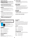
ikelite
SubstrobeSubstrobe
MOD-NC
serial number
serial number
FFoorr SSuubbssttrroobbee UUpp--DDaattee::
Contact Ikelite for information.