


GETTING STARTED
8
EN
MasterPage: Left
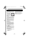
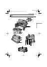
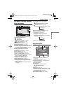
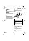
Controls
1
Rewind Button [1
] (
੬
pg. 20)
Left Button [
1
] (
੬
pg. 14)
Quick Review Button [QUICK REVIEW]
(
☞
pg. 19)
2
Set Button [SET] (
੬
pg. 14)
Data Battery Button [DATA] (
੬
pg. 12)
3
Stop Button [7
] (
੬
pg. 20)
Backlight Compensation Button
[BACKLIGHT] (
੬
pg. 28)
Down Button [
4
] (
੬
pg. 22)
4
Play/Pause Button [6
] (
੬
pg. 20)
Manual Focus Button [FOCUS] (
੬
pg. 27)
Up Button [
3
] (
੬
pg. 22)
5
Wide 16:9 Button [16:9] (
੬
pg. 26)
Blank Search Button [BLANK] (
੬
pg. 20)
6
Menu Button [MENU] (
੬
pg. 22)
7
Fast-Forward Button [¡
] (
੬
pg. 20)
Right Button [>] (
੬
pg. 14)
Night Button [NIGHT] (
੬
pg. 26)
8
Diopter Adjustment Control (
੬
pg. 15)
9
Auto Button [AUTO] (
੬
pg. 13)
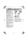
!
Snapshot Button [SNAPSHOT] (
੬
pg. 26)
"
Power Zoom Lever [T/W] (
੬
pg. 18)
Speaker Volume Control [VOL. +, –]
(
੬
pg. 20)
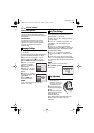
#Battery Release Button [PUSH BATT.]
(੬ pg. 11)
$Recording Start/Stop Button (੬ pg. 17)
%Power Switch [REC, OFF, PLAY] (੬ pg. 13)
&Lock Button (੬ pg. 13)
(Cassette Open/Eject Switch [OPEN/EJECT]
(੬ pg. 16)
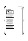
Connectors
The connectors are located beneath the covers.
Audio/Video Output Connector [AV]
(੬ pg. 21, 32)
DC Input Connector [DC] (੬ pg. 11)
Digital Video Connector [DV IN/OUT] (i.LINK*)
(੬ pg. 33, 34)
* i.LINK refers to the IEEE1394-1995 industry
specification and extensions thereof. The logo
is used for products compliant with the i.LINK
standard.
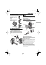
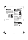
Indicators
POWER/CHARGE Lamp (੬ pg. 11, 17)
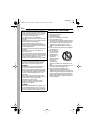
Other Parts
LCD Monitor (੬ pg. 18, 19)
Viewfinder (੬ pg. 15)
Battery Pack Mount (੬ pg. 12)
Shoulder Strap Eyelet (੬ pg. 11)
Speaker (੬ pg. 20)
Grip Strap (੬ pg. 14)
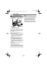
Lens
Camera Sensor
(Be careful not to cover this area, a sensor
necessary for shooting is built-in here.)
Stereo Microphone
Stud Hole (੬ pg. 15)
Tripod Mounting Socket (੬ pg. 15)
Cassette Holder Cover (੬ pg. 16)
GR-D350UC.book Page 8 Wednesday, October 19, 2005 1:51 PM