


CONTROLS, INDICATORS AND CONNECTORS
28
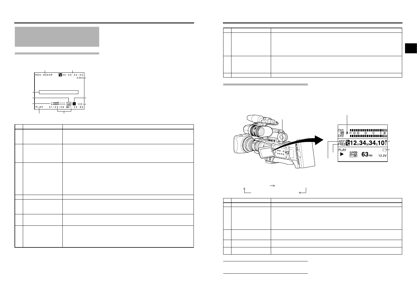
Indications on the LCD Monitor
and in the Viewfinder (Cont’d)
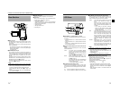
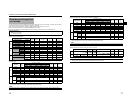
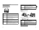
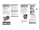
Status Screen in VTR MODE
1
2
3
9
4
5
6
7
8
0
No. Item Contents
1 VIDEO FORMAT display Displays the video format recorded on the tape when in VTR mode. Also displays the video format of the
HDV/DV input signal.
You can switch this display ON/OFF using the VIDEO FORMAT item on the LCD/VF[1/2] menu screen.
XSee page 91.
2 Time code (TC) and user’s bits
(UB) display
Displays the time code data being recorded (hour, minute, second, frame) when in VTR mode.
You can switch this display ON/OFF using the TC/UB item on the LCD/VF[1/2] menu screen.
XSee page 91.
You can select to display either the time code or the user’s bits using the TC DISPLAY switch in the LCD
door.
3 Remaining tape time Remaining tape indication (displayed in 1-minute steps)
This indicator blinks when remaining tape time is equivalent to less than 3 minutes.
Whether or not to display this item is set with the TAPE REMAIN item on the LCD/VF[1/2] menu screen.
XSee page 91.
* When inserting a brand-new tape, the remaining tape time is not indicated.
When the tape has been run, the indication will appear.
* The remaining tape indication is to be used only as a guide.
* When this device is used at low temperatures, it may take a while before the indication of the remaining
tape time appears.
4 Event display Displays messages related to VTR operations. X Seepages 106-108.
5 Audio sampling frequency in-
dication
The audio sampling frequency used for the recording is displayed during playback.
(32 K, 48 K, 44.1 K)
Whether or not to display this item is set with the AUDIO item on the LCD/VF[1/2] menu screen.
XSee page 91.
6 Audio level meter indication Displays the audio level meters during playback.
Whether or not to display this item is set with the AUDIO item on the LCD/VF[1/2] menu screen.
XSee page 91.
7 VTR mode indication Indicates the VTR operation status
STBY, STOP, PLAY, REC, FF, REW, FWD, REV, STL, - - - (No tape loaded), SLOW: During variable play-
back in forward direction (Displayed when using non-linear editing software.)
(SLOW+1: About ×0.1 speed, SLOW+2: About ×0.2 speed, SLOW+3: About ×0.5 speed)
During variable playback in reverse direction (Displayed when using non-linear editing software.)
(SLOW–1: About ×–0.1 speed, SLOW–2: About ×–0.2 speed, SLOW–3: About ×–0.5 speed)
29
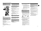
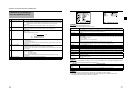
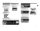
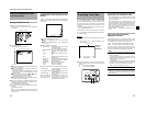
Magnified Status Indications on the
LCD Monitor
The characters on the status screens can be showed alone
in magnified size on the LCD monitor.
1.Set the LCD+VF item on the LCD/VF[4/4] menu screen to ON. X See page 92.
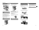
2.When the DISPLAY button is briefly pressed while the LCD monitor is displayed, the displayed contents change every time the
DISPLAY button is pressed.
MEMO
When characters indicating the status are displayed in
magnified size on the LCD monitor, the viewfinder display
the image.
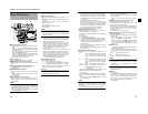
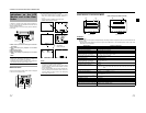
No. Item Contents
8 Time/Date indication Recorded data are displayed during playback, fast forward, and rewind.
During recording in DV format, the data from the IEEE1394 connector is displayed.
During recording in HDV format, the data of internal clock is displayed.
Whether or not the date and time should be displayed and the display style are set on the TIME/DATE
menu screen. X Seepage 95.
When the date and time have not been set, the following indication appears.
- -/- -/- - - -: - -: - -
9 Voltage indication (Example) 12.2V : Indicates remaining battery level in 0.1V steps.
Battery voltage and remaining battery are displayed. Select the display method in BATTERY INFO. on the
LCD/VF[1/2] menu screen XSee page 91.
Anton Bauer battery: Voltage/remaining capacity (%)/remaining time
IDX Endura battery : Voltage/remaining capacity (%)
0 Audio Lock indication Displayed when the audio signal from DV recording or playback is locked to the video signal.
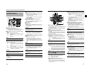
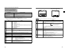
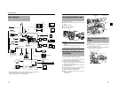
No. Item Contents
1 Audio Lock Indicator Displayed during recording and playback when the audio signal is locked to the video signal.
2 Time Code Generator Setting
Indicator
Indicates the set status of the TC GENE switch on the side section.
FREE : TC GENE switch is set to PRESET-FREE RUN MODE.
RECR : TC GENE switch is set to PRESET-REC RUN MODE.
REGN : TC GENE switch is set to REGEN MODE.
DUPL : There is 1394 input in VTR mode and TC DUPLI. menu is set to ON.
EXT : Displays when time code is input to the TC IN terminal.
(When TCG SOURCE on the TC/UB/CLOCK menu screen is set to EXTERNAL.)
3 Drop/Non-drop Indicator Indicates the framing mode of the time code.
DF : Drop frame mode
NDF : Non-drop frame mode
4 Synchronized display with an
external time code generator
Lights up when the time code generator of this device synchronizes with the time code input from the TC
IN terminal. Blinks when synchronization is unsuccessful. Turns off If there is no input signal.
5 Indication of DR-HD100 Oper-
ation
When a DR-HD100 (HDD unit by FOCUS enhancements) is connected, its operation status is displayed.
(For details, refer to the DR-HD100 INSTRUCTION MANUAL.)
266S
DD
DISPLAY button
1
3
2
5
4
Characters shown enlarged
Image and characters displayed
Only image displayed