


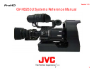

Version 1.10
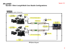
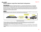
Section I Short Length Multi Core Studio Configurations
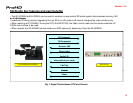
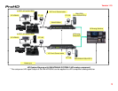
SD System Diagram
Fig 1 Signal Flow between CCU and Camera
Table of contents
Page
4
5
Fig
.
1
Signal
Flow
between
CCU
and
Camera
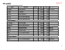
SD System Components price list
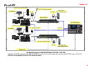
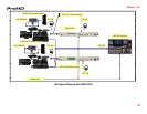
HD System Diagram with RM-HP250AU SYSTEM
HD System Diagram with RM-P210U
Fig 2 HD System Signal Flow between CCU and Studio Camera
HD S
y
stem com
p
onents
p
rice List
5
7
8
10
11
13
ypp
Section II Medium Length Fiber Cable Studio Configurations
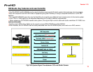
Camplex System Diagram
Shoulder/Tripod mounted CP301C/CP701C studio system diagram
Fig.3 Signal Flow between Camera Adapter and Base Station
Shoulder/Tripod mountable studio components price list
Sl d M t d GY
HD250U St di S t Di
15
17
18
19
20
Sl
e
d
M
oun
t
e
d
GY
-
HD250U
St
u
di
o
S
ys
t
em
Di
agram
Sled Mounted GY-HD250U studio system price list
Section III Long Length Fiber Cable connected Studio Configurations
Telecast Fiber system with Power
Hand Held/w power studio system diagram
Fig 4 Signal Flow between Camera Adapter and Base Station
20
22
24
25
26
Fig
.
4
Signal
Flow
between
Camera
Adapter
and
Base
Station
Hand Held/Tripod mounted with Power studio system price list
Sled Mounted/w Power studio system diagram
Sled mounted/w power studio system components price list
Extremely long length Telecast Fiber Studio System
Hand Held batter
y
p
owered studio s
y
stem dia
g
ram
26
27
28
30
32
33
yp y g
Hand Held battery powered studio system components price list
Sled Mounted with battery power studio system diagram
Sled Mounted with battery power studio system components price list
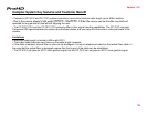
Section IV POV System configuration
POV Pan/Tilt System
POV S t C t P i Li t
34
35
36
38
39
2
POV
S
ys
t
em
C
omponen
t
s
P
r
i
ce
Li
s
t
39