


17
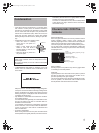
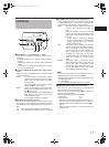
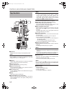
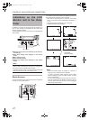
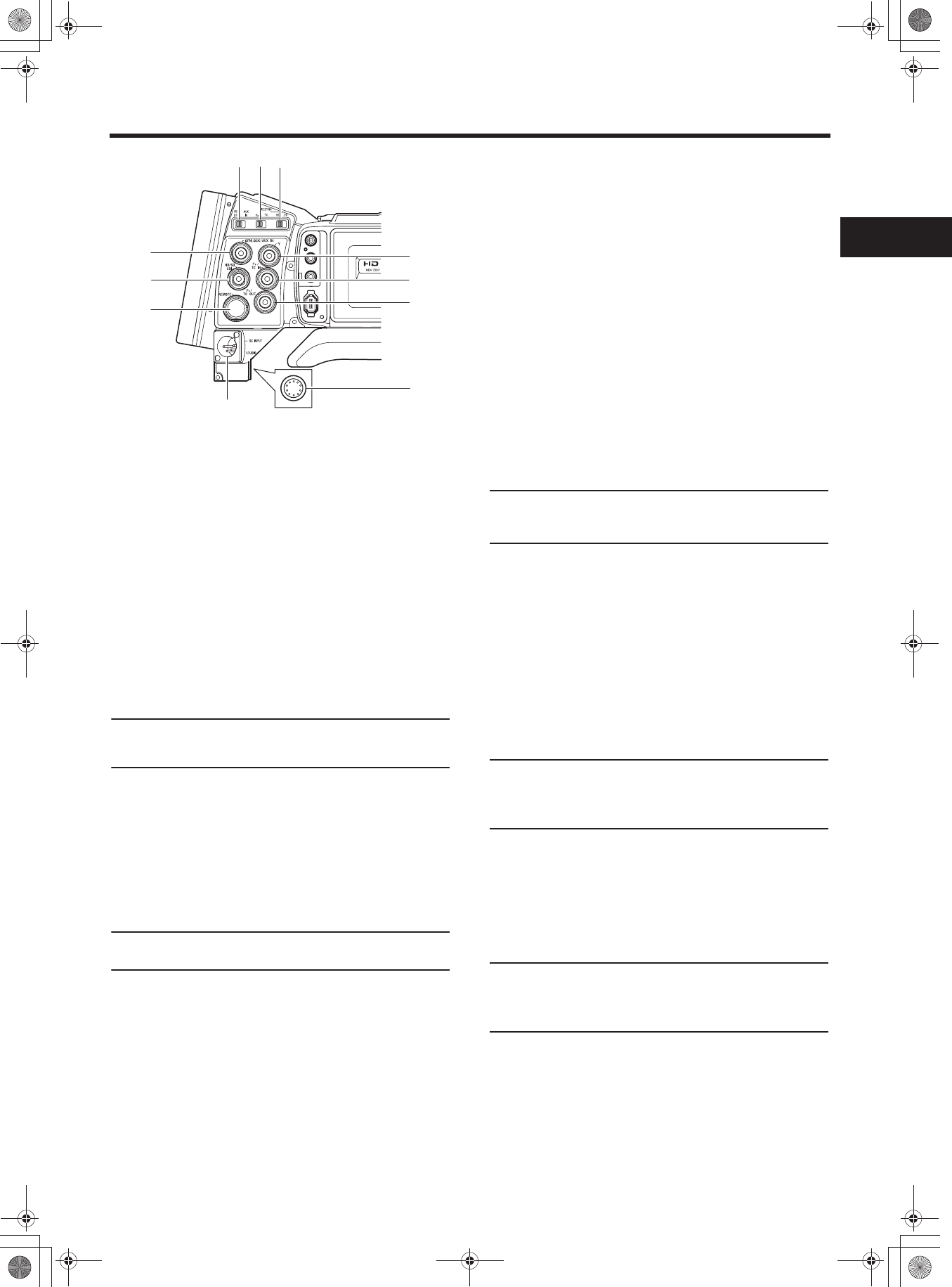
a[STUDIO] Studio terminal (Round 10-pin)
Connect the studio cable from the KA-HD250 Studio Kit
(sold separately). Connect the KA-HD250 to use this
device as a studio camera.
For details, refer to the KA-HD250 INSTRUCTION MAN-
UAL.
b[DC INPUT] DC input terminal (XLR 4-pin)
This is the 12V DC power input terminal. Connect to the
AC adapter.
When a battery is installed and a cable is connected to this
terminal, power supply from the battery stops and power is
supplied by this terminal.
c[GENLOCK/AUX IN] GENLOCK/AUX IN switch
Set according to the signal input in the [GENLOCK/AUX
IN] terminal.
GENLOCK : Set to this when inputting external synchroni-
zation signals.
AUX IN : Set to this when inputting composite video
signals from an external device.
MEMO
If no signals are input to the [AUX IN] terminal and this
switch is set to AUX IN, the monitor turns black and video is
not output from any terminal.
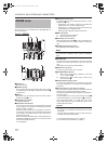
d[PBPR/TC] PBPR/Time code switch
Set according to the [P
B/TC IN] and [PR/TC OUT] terminal
signals.
P
BPR : Set to this when outputting component PB signals
from the [P
B/TC IN] terminal and outputting com-
ponent P
R signals from the [PR/TC OUT] terminal.
TC : Set to this when inputting LTC time code from the
[P
B/TC IN] terminal and outputting the built-in time
code generator from the [P
R/TC OUT] terminal.
MEMO
When this switch is set to TC, video is not output from the
Y/P
B/PR terminal (i j k).
e[IEEE1394] IEEE1394 switch
Set according to the image format of the input/output sig-
nal and playback signal of the IEEE1394 terminal.
HDV :Set to this for HDV format.
DV : Set to this for DV format.
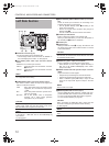
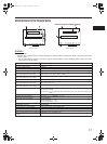
f[REMOTE] REMOTE terminal (Round 6-pin)
Some functions of this camera can be controlled exter-
nally.
Connect to a remote control unit (RM-LP55/RM-LP57).
X See “Connect a Remote Control Unit (RM-LP55/RM-
LP57)” on page 71.
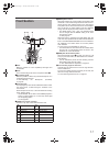
g[GENLOCK/AUX IN] GENLOCK/AUX IN terminal (BNC)
• Input synchronization signals in this terminal when
externally synchronizing camera images or playback
images.
Synchronization signal: BB (Black Burst) signal of SD
or Tri sync signal of HD
• Input composite video signals to record images from an
external device with this device.
• Select the signal to input with the [GENLOCK/AUX IN]
switch c.
X See “Using GENLOCK Functions” on page 66.
X See “Recording Composite Video Signals from an
External Device” on page 65.
h[HD/SD-SDI] HD/SD-SDI output terminal (BNC)
Outputs HD/SD-SDI (Serial Digital Interface) signals. Out-
puts embedded audio signals as digital audio.
The sampling frequency for embedded audio is 48 kHz.
In addition, the time code for the built-in time code genera-
tor and playback time code are output.
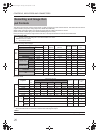
X See pages 20 and 21 for the signals that are enabled.
MEMO
Set whether or not to output SDI signals from this terminal
in HD/SD-SDI OUT of the VIDEO FORMAT[2/2] menu
screen.
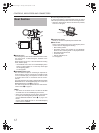
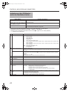
i[Y] Component Y signal output terminal (BNC)
Outputs Y signal of component when the [P
BPR/TC] switch
d is set to PBPR.
j[P
B/TC IN] Component PB signal output/time code
input terminal (BNC)
• Outputs P
B signal of component when the [PBPR/TC]
switch d is set to P
BPR.
• Inputs time code when the [P
BPR/TC] switch d is set to
TC. Enter the LTC time code to slave lock this device’s
time code generator with an external time code genera-
tor.
MEMO
Set TCG SOURCE on the TC/UB/CLOCK Menu screen to
EXTERNAL to input external time codes.
X See “Synchronizing with an External Time Code Gener-
ator” on page 49.
k[PR/TC OUT] Component PB signal output/time code
output terminal (BNC)
• Outputs P
R signal of component when the [PBPR/TC]
switch d is set to PBPR.
• Outputs the LTC time code of the built-in time code gen-
erator when the [P
BPR/TC] switch d is set to TC.
MEMO
Set the [Y/P
B/PR] terminal (i j k) output image signal to
RGB or Y/C video signals in OUTPUT TERM. [DV] on the
VIDEO FORMAT[2/2] menu screen. (Only for DV format)
X See “OUTPUT TERM. [DV]” on page 79.
IEEE 1394
CH2-AUDIO OUT-CH1 VIDEO
g
b
c
d
e
f
j
i
h
k
a
e_hd250.book Page 17 Tuesday, October 24, 2006 3:11 PM