


49
Synchronizing with an Exter-
nal Time Code Generator
Synchronize the built-in time code generator with the
SMPTE/EBU-compliant LTC time code, which is input from
the [TC IN] terminal. After synchronization (slave lock), the
built-in time code generator continues to run even if external
time code are not input.
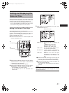
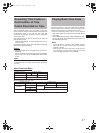
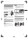
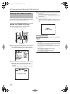
Connection
Input external synchronization signal to the external time
code generator and the GENLOCK/AUX IN terminal of this
device.
Use BB signals or Tri-sync HD signals as the external syn-
chronization signals.
CAUTION
When the power switch is turned on while the external syn-
chronization signal is input, a vertical vibration occurs for a
few seconds. This is not a malfunction.
Input SMPTE/EBU-compliant LTC time code signal to the
PB/TC IN terminal.
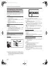
Setting
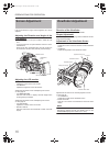
Set the [GENLOCK/AUX IN] switch to GENLOCK.
Set the [P
BPR/TC] switch to TC.
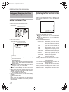
Set TCG SOURCE in the TC/UB/CLOCK menu screen to
EXTERNAL.
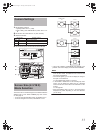
Set the LCD screen or viewfinder to STATUS 1 screen dis-
play.
Or set the LCD screen to enlarged status display screen.
X See page 29.
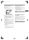
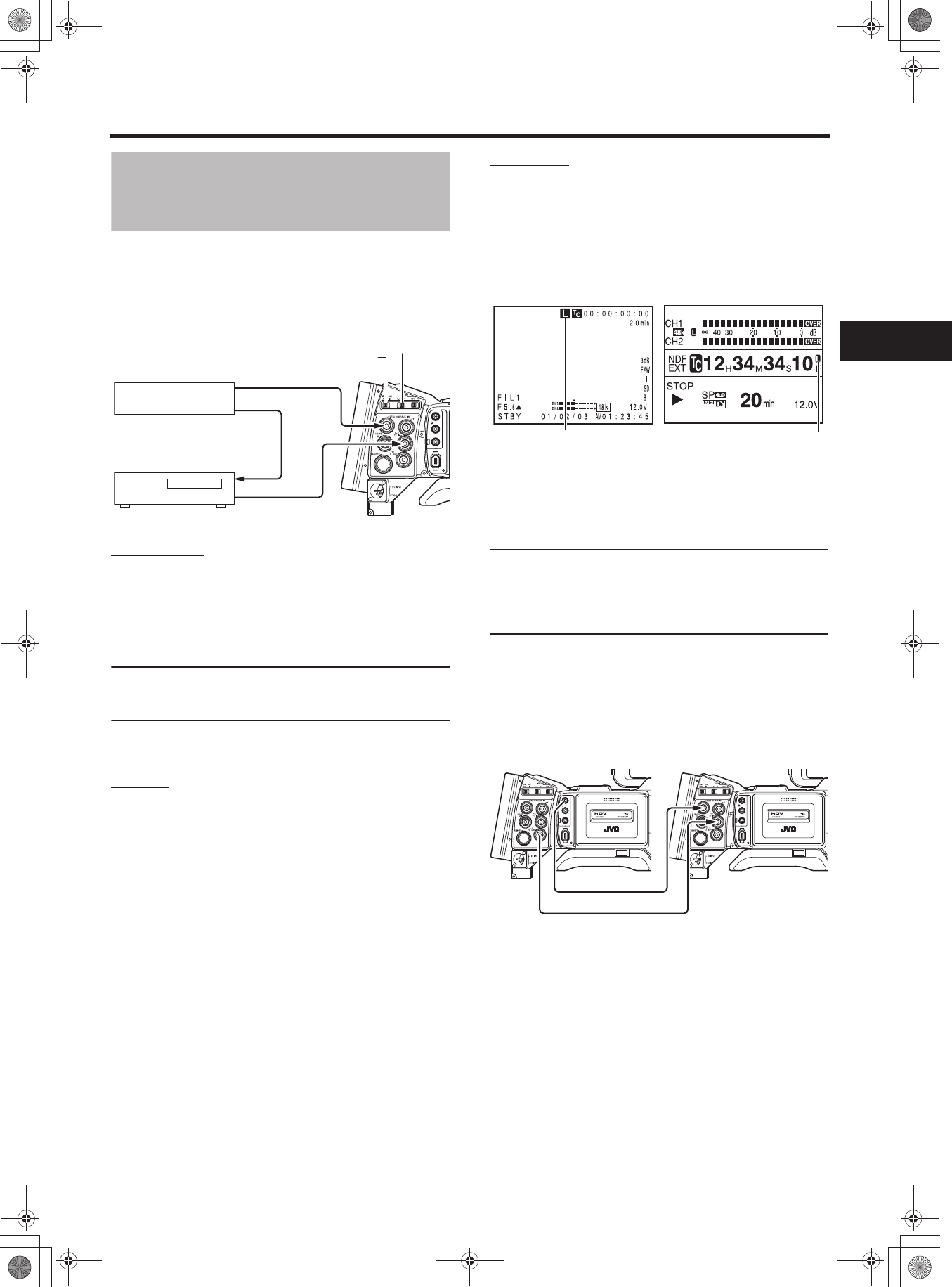
Operation
1. Set the external time code generator and operate it.
• The built-in time code generator synchronizes with the
input external time code data.
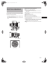
“L” lights up in the STATUS 1 screen of LCD screen or
viewfinder. ”L” also lights up when the LCD screen is in
enlarged character display.
• “L” blinks when the time code cannot be synchronized.
2. The built-in time code generator continues to run even if
the external time code generator is disconnected after
synchronization.
CAUTION
• If a time code generator is connected or disconnected
during recording, servo lock will be disturbed.
• The user's bit data range for an input external time code
generator is 00 00 00 00 to FF FF FF FF.
When FF FF FF FF is entered, FF FF FF FF is recorded.
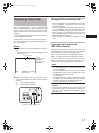
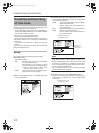
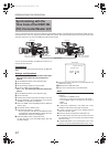
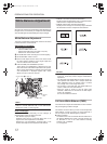
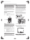
When connecting multiple devices and assigning one
as the master unit and others as slave units
If there is only one slave unit, connect as shown below.
If there are multiple slave units, input external synchroniza-
tion signals to all GENLOCK/AUX IN terminals from the syn-
chronization signal generator.
IEEE 1394
CH2-AUDIO OUT-CH1 VIDEO
Synchronization signal
generator
Synchronization signal
LTC time code
External time code
generator
Synchronization signal
TC IN
GENLOCK
IN
GENLOCK/AUX IN switch
P
BPR/TC switch
STATUS 1 screen
Lights up
Enlarged display screen
Lights up
IEEE 1394
CH2-AUDIO OUT-CH1 VIDEO
IEEE 1394
CH2-AUDIO OUT-CH1 VIDEO
Master unit
VIDEO OUT
Slave unit
TC IN
TC OUT
GENLOCK IN
e_hd250.book Page 49 Tuesday, October 24, 2006 3:11 PM