


USING EXTERNAL COMPONENTS
66
Using GENLOCK Func-
tions
This device features a GENLOCK IN terminal. Input external
synchronization signals in the GENLOCK IN terminal to syn-
chronize camera images or playback images with external
signals.
Additionally, the H (horizontal) and SC (subcarrier) phase
adjustments can be performed on image signals of this
device for external synchronization signals from the GEN-
LOCK menu screen.
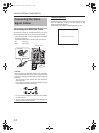
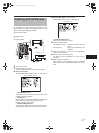
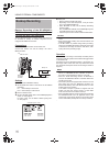
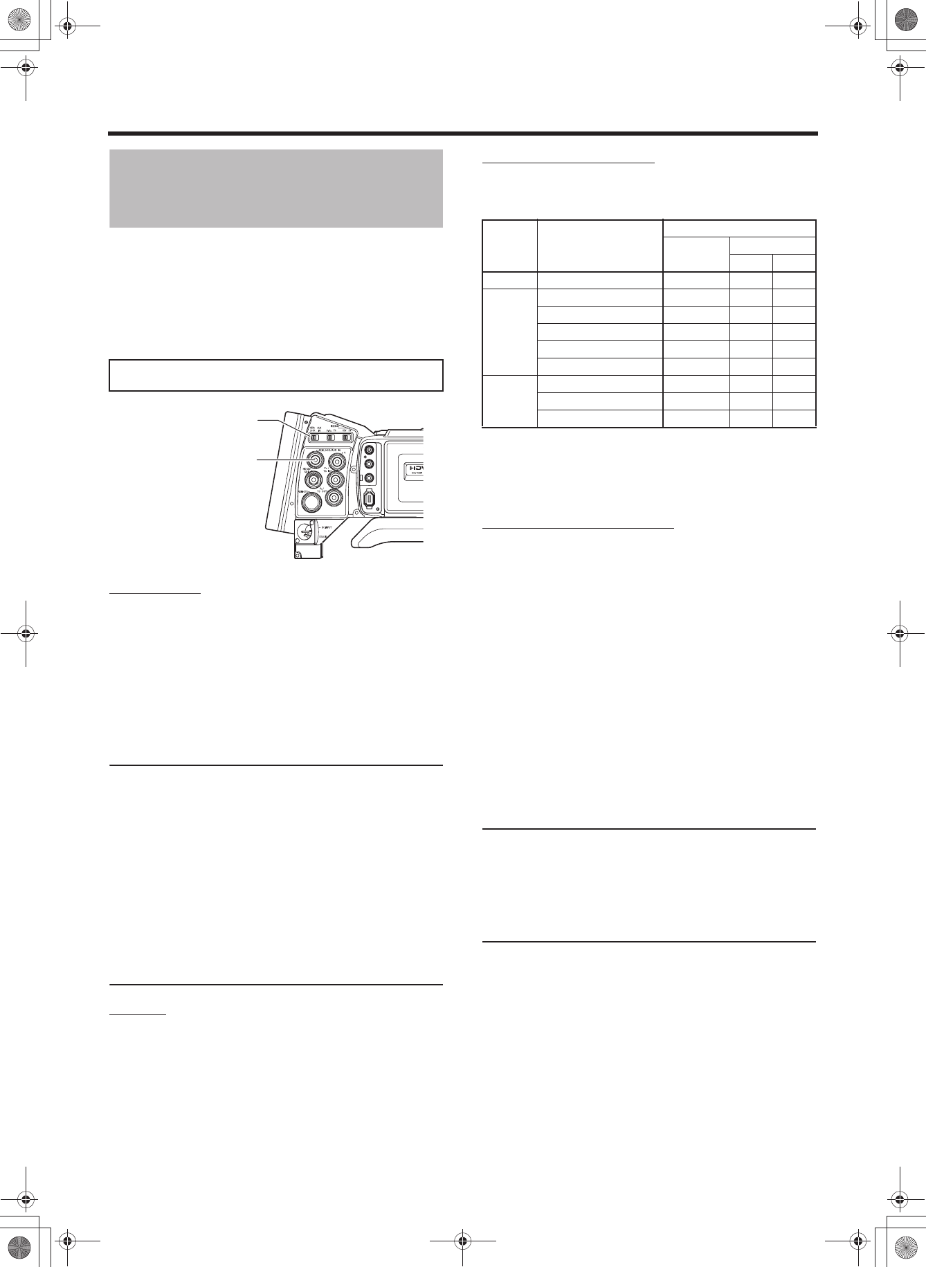
Connection
During Standby or Stop mode, input synchronization sig-
nals from a Sync signal generator to the GENLOCK/AUX
IN terminal.
The following synchronization signals are applicable.
SD synchronization signal: BB (Black burst) signals
SMPTE170M (RS-170A)-compliant for NTSC
ITU-R BT.470-6-compliant for PAL
HD synchronization signal: HDTV Tri-sync signals
SMPTE296M-compliant for HD720p
SMPTE274M-compliant for HD1080i
CAUTION
• When the FRAME RATE is set to 60/30 or 24 in the
VIDEO FORMAT[1/2] menu screen, input a 59.94 Hz
synchronization signal (vertical synchronization). 50 Hz/
60 Hz synchronization signals cannot be synchronized.
If the FRAME RATE is set to 50/25, input a 50 Hz syn-
chronization signal. 59.94 Hz/60 Hz synchronization sig-
nals cannot be synchronized.
• Do not connect or disconnect the cable during recording
or playback.
• When the power is turned on while the external synchro-
nization signal is input, a vertical vibration occurs for a
few seconds. This is not a malfunction.
• VTR playback signals with jitter cannot be synchronized
with this device.
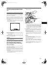
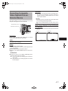
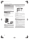
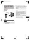
Setting
Set this device to Camera mode.
Set the GENLOCK/AUX IN switch to GENLOCK.
• When the camera image is locking to external synchro-
nization signals, “SYNC LOCKING” is displayed on the
screen. When locking to external synchronization sig-
nals is complete, the indication disappears and you can
enter recording mode.
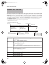
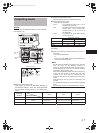
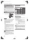
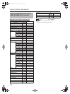
Synchronized Signals
The synchronized signal differs depending on the input sync
signal.
Refer the table below.
SC : Subcarrier phase H: Horizontal phase
V : Vertical phase F : Field phase
Adjust SC PHASE and H PHASE in the above table from the
GENLOCK menu screen.
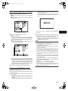
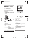
Adjust SC and H PHASE
1. Display the GENLOCK menu screen.
Follow the steps in “Setting Menu Screens” on page 75
and proceed as follows.
MENUrOTHERSrGENLOCK
2. In the GENLOCK menu screen, select the item to per-
form phase adjustment for and adjust.
SD H PHASE : Adjust the H phase in SD analog signals.
(During BB signal input)
HD H PHASE : Adjust the H phase in HD analog and SD/
HD SDI signals. (During Tri-sync signal
input, PHASE of SD analog signals are
simultaneously adjusted in HD H PHASE
item.)
SC PHASE : Adjust the SC phase in composite and
YC signals.
For details, refer to “GENLOCK Menu Screen” on
X See page 99.
MEMO
• H PHASE cannot be adjusted during playback or record-
ing.
• IEEE1394 output stops while H PHASE is being
adjusted.
• When values for SD H PHASE or HD H PHASE is
changed, the images cannot be produced properly
momentarily. This is not a malfunction.
GENLOCK functions are only valid in Camera mode. They do not
work in VTR mode.
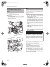
IEEE 1394
CH2-AUDIO OUT-CH1 VIDEO
GENLOCK/AUX IN switch
GENLOCK/AUX IN terminal
Terminal Video signal
Input sync signal
BB
Tri-sync
720p 1080i
VIDEO Composite SC,H,V,F V V,F
Y/P
B/PR
SD Component H,V,F V V,F
HD Component 720p V H,V V
HD Component 1080i V,F V H,V,F
SD RGB H,V,F V V,F
SD Y/C SC,H,V,F V V,F
HD/SD-
SDI
SD-SDI H,V,F V V,F
HD-SDI 720p V H,V V
HD-SDI 1080i V,F V H,V,F
e_hd250.book Page 66 Tuesday, October 24, 2006 3:11 PM