


CONTROLS, INDICATORS AND CONNECTORS
16
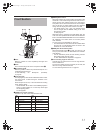
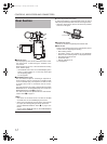
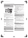
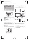
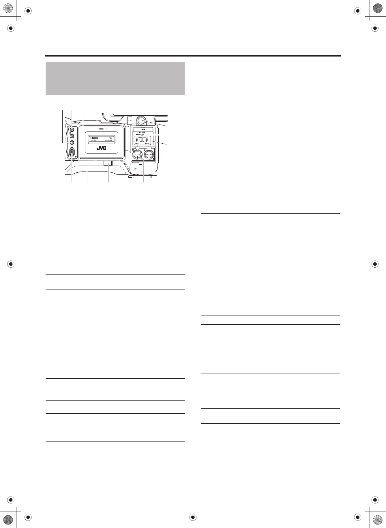
Left Side Section
1Viewfinder connector (6-pin)
Connect the cable from the viewfinder here.
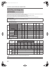
• Set the image format for this terminal in VF SIGNAL on
the LCD/VF[4/4] menu screen. X See page 92.
2[CH-2 INPUT] CH-2 audio input connector selector
switch
Selects the CH-2 audio input connector.
MEMO
The audio from the INPUT1 connector is also input into
CH-1 regardless of the setting.
3[AUDIO INPUT] Audio input signal selector switch
This switch is used to select the input sound signal from
INPUT1 or INPUT2 connector.
CAUTION
When connecting a component that does not require +48 V
power supply, make sure that the switch is not set to
MIC+48V before the component is connected.
MEMO
You can select the normal input level for MIC and MIC+48V
in the INPUT1, 2 MIC REF. item on the AUDIO/MIC[1/2]
menu screen.
X See page 87.
4[INPUT1/INPUT2] INPUT1/INPUT2 audio input connec-
tors
These are audio input connectors for connecting to an
external audio device or microphone.
• Set the [AUDIO INPUT] switch 3 according to the
device to be connected.
• Set the CH-2 audio input connector using the [CH-2
INPUT] switch 2.
The CH-2 audio from the set connector is recorded.
5Shoulder pad slide button
Button to adjust the position of the shoulder pad.
When you press this button, you can move the position of
the shoulder pad 6 forward or backward.
6Shoulder pad
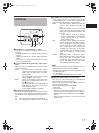
7Cassette cover
Sliding the EJECT switch a on page 18 located on the
top section opens this cover to allow insertion or removal
of the videocassette.
CAUTION
To prevent foreign objects from entering the internal parts of
the VTR unit, do not leave this device with the cover open
for extended periods of time.
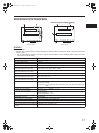
8[VIDEO OUT] Video output terminal (RCA)
This is a terminal for composite video signal output.
• Select whether or not to output a signal with setup in
SET UP on the VIDEO FORMAT[2/2] menu screen.
(Only for U model)
9[AUDIO OUTPUT CH-1/CH-2] Audio output connector
(RCA)
Output connector for audio signals.
• Outputs the input audio signal in the Camera mode.
• Outputs the playback audio signal in the VTR mode.
• When a HDV/DV signal (IEEE1394) is input, the EE
sound of the input audio signal is output in the VTR
mode.
MEMO
Alarm sound is not output.
0[IEEE1394] IEEE1394 connector (6-pin)
Using an IEEE1394 cable (optional), a digital video com-
ponent with IEEE1394 connector can be connected here.
X See “Connecting the IEEE1394 Cable” on page 64.
X See “HDV/DV Dubbing” on page 68.
CAUTION
When connecting the IEEE1394 cable, confirm that the
connector is facing the right direction before inserting.
X Seepage64.
MEMO
Put the covers on the connectors when you are not using
them.
INPUT1 : Inputs the audio from the INPUT1 connector
4 into CH-2.
INPUT2 : Inputs the audio from the INPUT2 connector
4 into CH-2.
LINE : Set to this position when connected to audio
equipment, etc. The reference input level is
+4 dBs.
MIC : Set to this position when the dynamic micro-
phone is connected.
MIC+48V : Set to this position when a microphone
requiring +48 V power supply (phantom
microphone, etc.) is connected.
IEEE 1394
CH2-AUDIO OUT-CH1 VIDEO
0
98 7
1
2
3
456
e_hd250.book Page 16 Tuesday, October 24, 2006 3:11 PM