


13
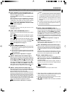
Adjustments for Genlock Operation
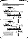
Genlocking is required for a system, which uses an SEG (special effects generator) as the main
signal source.
REF.
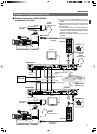
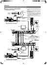
: “Example of Connection with 2 Units” on page 9.
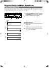
Preparations and Main Functions
Preparation
1.
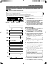
Press the BARS button to output the color bar signal. The
button light should light up.
2.
Output the built-in color bar signal of the SEG from the
program connector on the front panel of the SEG. (Refer
to the INSTRUCTIONS MANUAL of the SEG.)
3.
Observing the monitor screen at the same time, adjust
the H PHASE (horizontal phase) and SC (subcarrier
phase) while using the switch on the SEG to alternately
change between color bars of the internal RM-HP250 that
of the SEG.
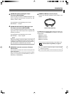
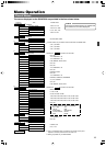
Adjusting the H PHASE
4.
Press and hold the MENU button for about 3 seconds until
the LCD display shows the menu display.
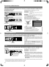
5.
Ensure that the cursor ( ) is located on “1: GENLOCK”,
then press the control knob to display “1A: SD H PHASE”
or “1B: HD H PHASE”.
6.
Press the control knob to move the cursor ( ) to the cur-
rently set value, then turn the control knob to adjust the H
PHASE value (HD: –1024 to 1023, SD: –128 to 127).
After the adjustment, press the control knob to move the
cursor (
) back to “1: GENLOCK”.
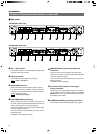
M
FULL AUTO F1
SHUTTER
GAIN
F2
F3
MENU/SHUTTER GAIN
P
R
STEP
SHUTTER
MENU
PUSH-ON
DOWN UP
VARIABLE
PUSH-ON
HIGH
LOW
MID
DOWN UP
F4
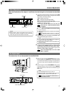
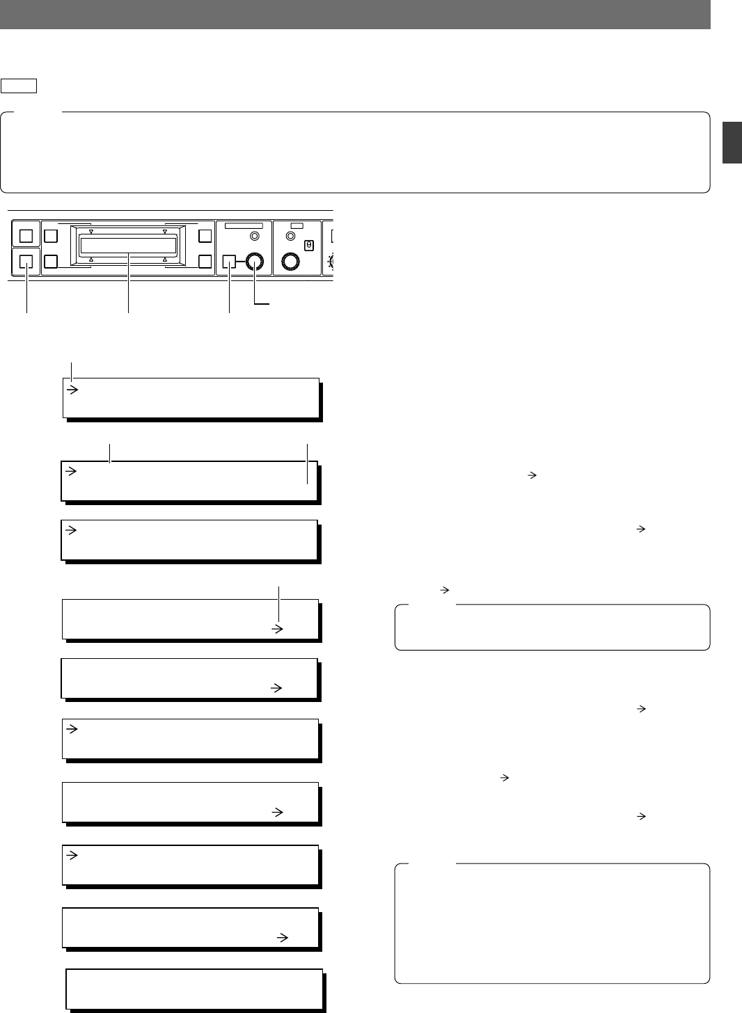
BARS
LCD displayBARS button MENU button
Control knob
1: GENLOCK
2: CABLE
1: GENLOCK
2: CABLE
4.
Cursor
1A: SD H PHASE
0
5A.
Item Setting
6A.
1A: SD H PHASE
127
Cursor
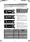
7.
1C: SC COARSE
0
°
8.
1C: SC COARSE
90
°
9.
1D: SC FINE
0
10.
1D: SC FINE
127
11.
STR
CMP
OFF
0 dB
ALC
LUX
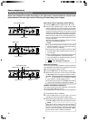
● The following adjustments can be made more accurately when using a vectorscope and waveform monitor.
● Be sure to use an underscanned video monitor.
● It is not permitted to genlock the system components using a VCR playback signal.
● Before phase adjustment, wait a little for the phases of the connected components to stabilize.
NOTE
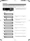
SC COARSE and SC FINE are linked.
When the upper or lower limit of SC FINE is exceeded,
the value of SC COARSE changes.
For example, when the value of SC COARSE is 0° and
SC FINE is increased, once SC FINE exceeds 127, SC
COARSE will become 90° and SC FINE will become -
128.
NOTE
1B: HD H PHASE
0
5B.
6B.
1B: HD H PHASE
1023
Screens 5 and 6 differ according to the VIDEO FORMAT
of the camera.
NOTE
11
.
After the adjustment, press the MENU button to return to
the previous display.
12
.
Press the BARS button to stop the color bar signal output.
Adjusting SC phase (Only for SD signal)
7.
Turn the control knob to display “1C: SC COARSE”.
8.
Press the control knob to move the cursor ( ) to the cur-
rently set value, then turn the control knob to adjust the
SC COARSE value (to 0°, 90°, 180° or 270°).
9.
After the coarse adjustment, press the control knob to
move the cursor (
) back to “1C: SC COARSE”, then
press the control knob to display “1D: SC FINE”.
10
.
Press the control knob to move the cursor ( ) to the cur-
rently set value, then turn the control knob to adjust the
SC FINE value (from -128 to 127).