


17
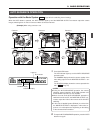
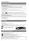
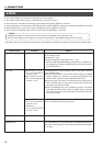
When an alarm signal is received, this unit performs the following operations.
<Alarm priority mode>
● The video is switched to the camera position from which the alarm signal is received.
● An alarm signal will automatically override and cancel the operation of either AUTO PATROL or AUTO SEQUENCE. (AUTO
SEQUENCE: In A mode only.)
● The preset alarm title is displayed in the preset size.
● The ALARM indicator blinks and the buzzer sounds. ( REF. : “BUZZER TIME” on page 32 for the setting method.)
● The CAMERA display indicates the number ID of the camera which has given the alarm signal.
● The UNIT ALARM output is turned ON.
<Manual priority mode>
● When an alarm signal is received during manual operation (except during the AUTO PAN, AUTO PATROL and AUTO SE-
QUENCE operations), the alarm operation does not start.
● When an alarm signal is received from a camera other than the camera being controlled manually, the alarm operation starts
but, unlike in the alarm priority mode, the buzzer does not sound and the camera in question is not automatically selected.
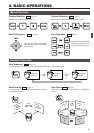
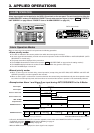
3. APPLIED OPERATIONS
ALARM OPERATION
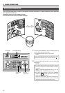
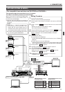
Alarm input signals can be applied to the DATA I/O terminals on the rear panel. The unit functions in either the
ALARM PRIORITY mode or the MANUAL PRIORITY mode when an alarm signal is input. ( REF. : “CONTROL
UNIT SCREEN” on page 28 and “PRIORITY item of ALARM SCREEN” on page 32.)
Alarm Operation Modes
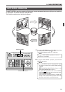
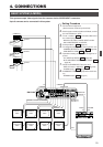
• In B mode, the MONITOR OUTPUT 2 connector outputs the same video as the MONITOR OUTPUT 1 connector.
For B Mode connection. REF. : [Applied System (B Mode)] on page 21.
B Mode output signal REF. : [B Mode] on page 22.
• While the MENU screen is displayed, the alarm signal is not accepted.
1
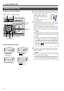
TO CAMERATO CAMERA DATA I / ODATA I / O
RX
+
RX
-
TX
+
TX
-
COMCOM
1 2 3 4 5 6 7 8
COMCOM
9/19/1 10/210/211/311/3 12/412/413/513/5 14/614/6 15/715/716/816/8
COMCOM COMCOM COMCOM
CAMERACAMERA
SWSW
UNITUNIT
ALARMALARM
AUTOAUTO
4312 8756
2 3 4 5 6 7
8
1
MONITORMONITOR
OUTPUTOUTPUT
MONITORMONITOR
SERIAL-2SERIAL-2SERIAL-1SERIAL-1
VIDEO INPUTVIDEO INPUT
VIDEO OUTPUT
OUTPUTOUTPUT
2
1
ON
2 3 4 5 6 7
8
POWER
OFF
ON
AC INPUT
`
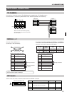
DATA I/O terminals
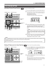
Alarm input 2
Alarm input 1
Alarm input 2
Camera 1 alarm time
Camera 2 alarm time
UNIT ALARM
output duration
MONITOR OUTPUT 1
MONITOR OUTPUT 2
CAMERA2 CAMERA3
CAMERA3 CAMERA2
CAMERA3
CAMERA4
CAMERA CAMERA
CAMERA CAMERA
CAMERA4 CAMERA5 CAMERA6 CAMERA7
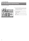
ALARM TIME
ALARM TIME
Set in item "TIME" in the AUTO SEQUENCE screen.
Time period of switching by CAMERA SW.
*Encircled number shows the alarm condition.
Time
Alarm input 1
SETUP
MENUMENU SET
SPEED
IRISIRIS
AFAF
FOCUSFOCUS
ZOOMZOOM
OPENOPEN
FAR
TELE CLEAR
/HOME/HOME
7
4
1
8
0
5
2
9
6
3
ENTER
AUTOAUTO
PANPAN
OPTIONOPTION
1
OPTIONOPTION
2
CAMERACAMERA
POSI-POSI-
TION
AUTOAUTO
PATROLPATROL
CLOSE
NEARNEAR
WIDEWIDE
AUTOAUTO F-1 F-2 F-3F-3
PAN/TILTPAN/TILTLENSLENS
CAMERA/POSITIONCAMERA/POSITION
CAMERACAMERA POSITIONPOSITION
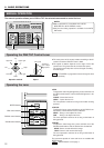
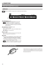
REMOTE CONTROL UNIT REMOTE CONTROL UNIT
RM-P2580RM-P2580
ALARM
POWER
KEY LOCK
<Example when Alarm 1 and Alarm 2 are input during AUTO SEQUENCE in the A Mode>