


18
CAMERA SWITCHING OPERATION
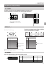
DATA OUTPUT
3. APPLIED OPERATIONS
ALARM OPERATION (Continued)
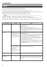
Clearing the alarm
The alarm operation can be cleared in two ways:
1
TO CAMERATO CAMERA DATA I / ODATA I / O
RX
+
RX
-
TX
+
TX
-
COMCOM
1 2 3 4 5 6 7 8
COMCOM
9/19/1 10/210/211/311/3 12/412/413/513/5 14/614/6 15/715/716/816/8
COMCOM COMCOM COMCOM
CAMERACAMERA
SWSW
UNITUNIT
ALARMALARM
AUTOAUTO
4312 8756
2 3 4 5 6 7
8
1
MONITORMONITOR
OUTPUTOUTPUT
MONITORMONITOR
SERIAL-2SERIAL-2SERIAL-1SERIAL-1
VIDEO INPUTVIDEO INPUT
VIDEO OUTPUT
OUTPUTOUTPUT
2
1
ON
2 3 4 5 6 7
8
POWER
OFF
ON
AC INPUT
`
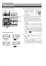
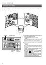
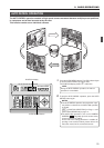
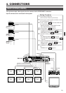
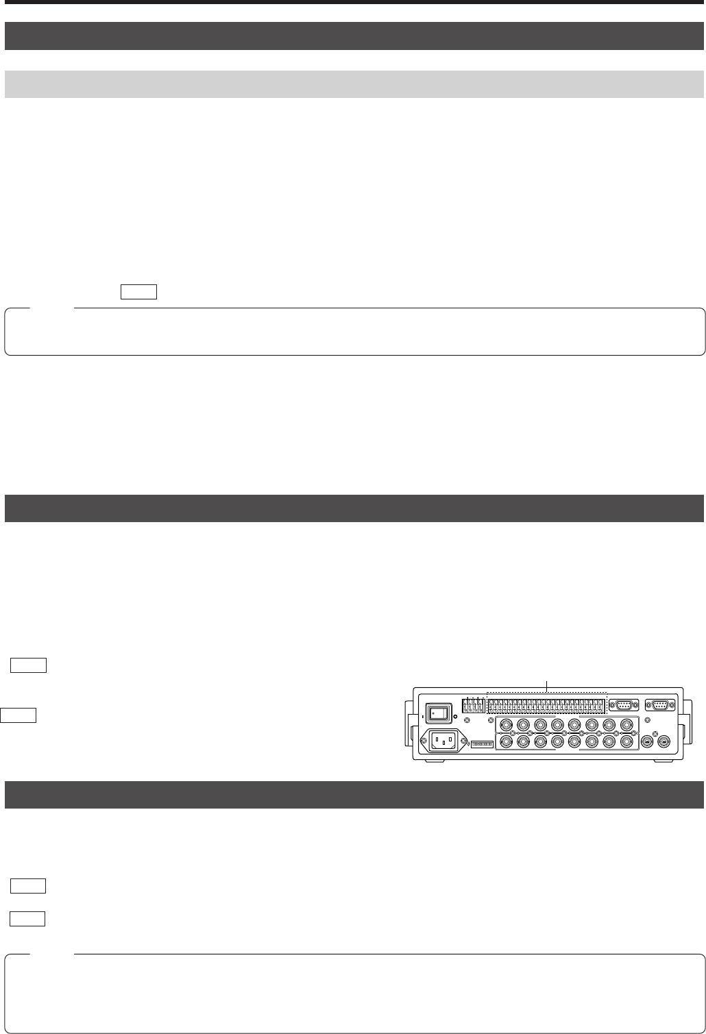
DATA I/O terminals
Three terminals, AUTO, UNIT ALARM and SELECT OUT / ALARM are provided at the Data Output terminal.
● AUTO terminal
Signals are output when the AUTO SEQUENCE starts.
● UNIT ALARM terminal
Signals are continuously output during an ALARM occurrence.
● SELECT OUT / ALARM terminal
When a particular camera or camera position is selected by using a combination of the numeric keypad and the CAMERA,
POSITION buttons, the corresponding command signal is output via one of the DATA I/O terminals on the rear panel.
REF. : See “DATA I/O SCREEN” on page 30, 31 for the assignment of each terminal.
For details of signal types to be output from each terminal;
REF. : Page 20 for the A Mode, and page 22 for the B Mode.
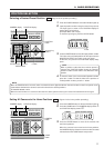
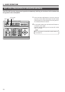
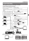
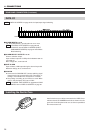
By means of a CAM SW signal from a Time Lapse VCR which is connected to the CAMERA SW terminals, the video signal from
MONITOR OUTPUT 2 can be selected to feed the Time Lapse VCR.
● When switching the video signal with the CAM SW, be sure to set the CAMERA SELECTION item to ENABLE. Otherwise the
video signal will not be switched correctly.
REF. : “OPTION SCREEN: CAMERA SELECTION” on page 29.
● Setting alterations are necessary according to which time-lapse VCR is connected.
REF. : “CONTROL UNIT SCREEN” on page 28 and “DATA I/O screen: CAM SWITCH Item” on page 30
Set the CAM SWITCH to LOW when a time-lapse VCR of JVC is connected.
NOTE
To switch the Alarm signal correctly by the CAM SW signal, set it in the following manner:
● Make sure that video signals are input to VIDEO INPUT 1.
● Make sure that the recording hours for the time-lapse VCR are set for 24 hours or more.
● Make sure the CAMERA SELECTION item is set to ENABLE for VIDEO INPUT 1.
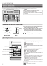
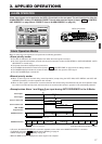
<Stopping the alarm operation manually>
When the alarm signal is received by the camera currently being selected, the alarm operation can be stopped by pressing the ENTER
button. If the alarm signal is received by different camera, select that camera and press the ENTER button to stop the alarm operation.
● The ALARM indicator turns off.
● The buzzer sound stops.
● The alarm title display clears.
● The UNIT ALARM maintains the MAKE position until the alarm conditions for all the cameras have been cleared.
NOTE
When the ALARM TIME is set to SERIES, the alarm condition continues until the preset position, of the camera to which the
alarm signal was input, is selected.
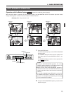
<The alarm operation stops automatically when specified time has elapsed>
When the time period specified in the ALARM TIME item in the ALARM screen has elapsed, the alarm operation stops automatically.
● The ALARM indicator turns off.
● The buzzer sound stops.
● The AUTO SEQUENCE mode returns to its situation before the alarm input. (A mode only)
● The camera which received the alarm signal returns to its setting before the alarm input. (AUTO PAN, AUTO PATROL or home
position)
● The alarm title display clears.
● The UNIT ALARM maintains the MAKE position until the alarm conditions for all the cameras have been cleared.
To set the alarm time REF. : [CONTROL UNIT SCREEN] on page 28 and [ALARM SCREEN : ALARM TIME] on page 32.