


8
›
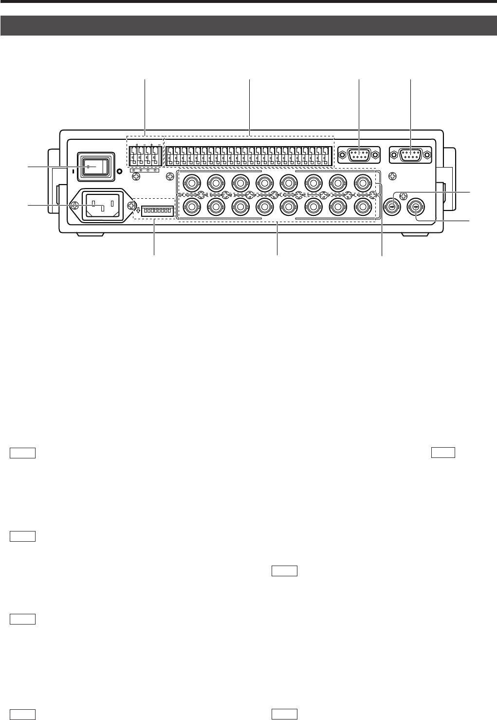
[AC
`
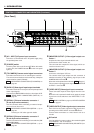
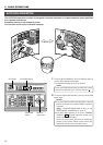
INPUT] AC power input connector
Connect to a conventional 120 V AC power supply using
the provided power cord.
fi
[POWER] switch
Turns the power of the unit ON and OFF. When this switch
is set to ON, the POWER indicator
4
on the front panel
lights up.
fl
[TO CAMERA] Camera control signal connectors
Connection terminals for use in controlling the cameras.
The control communications use the multi-drop, full-duplex
communication system (RS-485).
REF. :“REAR PANEL CONNECTORS (TO CAMERA)” on
page 23.
‡
[DATA I/O] Data signal input/output terminals
Connection terminals for use by the alarm input/output and
select output signals.
Connect the CAMERA SW terminal to a time-lapse VCR.
REF. : “REAR PANEL CONNECTORS (DATA I/O)” on
page 24.
[SERIAL-1] External extension connector 1
(D-sub 9-pin male connector)
Use this connector when connecting an external compo-
nent such as an alarm unit.
REF. :“REAR PANEL CONNECTORS (SERIAL-1, -2)” on
page 23.
Contact your JVC sales agent for details.
·
[SERIAL-2] External extension connector 2
(D-sub 9-pin male connector)
Use this connector when controlling a frame switcher (SW-
D7000/SW-D8000).
REF. :“REAR PANEL CONNECTORS (SERIAL-1, -2)” on
page 23.
‚
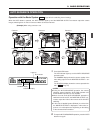
[MONITOR OUTPUT 1] Video signal output con-
nector 1
Outputs the video signal selected with this unit.
Connect to the video monitor, etc.
This connector also outputs the video signal, which car-
ries the on screen menu.
¡
[MONITOR OUTPUT 2] Video signal output con-
nector 2
Connect to a time-lapse VCR, etc.
The camera video signal output from this connector is
switched according to the switching signal input at the
CAMERA SW IN terminal
‡
.
When this unit is operated in the B mode ( REF. : Page 21):
This connector outputs the same signal as the MONITOR
OUTPUT 1 connector
‚
.
™
[VIDEO INPUT] Video signal input connectors
These connectors input the video signals from the cam-
eras.
When this unit is operated in the B mode, apply the output
signal from a frame switcher to the VIDEO INPUT 1 con-
nector.
REF. :“BASIC SYSTEM” on page 19, “APPLIED SYSTEM”
on page 21.
£
[VIDEO OUTPUT] Video signal output connectors
Each of these connectors outputs the video signal corre-
sponding to the VIDEO INPUT connector
™
above it.
Connect these connectors to a video device such as a
monitor.
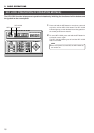
¢
DIP switch
Used to switch the system mode or the standard applied
to the SERIAL-1 and -2 connectors.
REF. :“REAR PANEL CONNECTORS (DIP SWITCH)” on
page 23.
1. INTRODUCTION
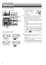
CONTROLS, CONNECTORS AND INDICATORS (Continued)
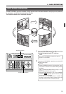
[Rear Panel]
1
TO CAMERATO CAMERA DATA I / ODATA I / O
RXRX
+
RXRX
-
TXTX
+
TXTX
-
COMCOM
1 2 3 4 5 6 7 8
COMCOM
9/19/1 10/210/211/311/3 12/412/413/513/514/614/615/715/716/816/8
COMCOM COMCOM COMCOM
CAMERACAMERA
SWSW
UNITUNIT
ALARM
AUTOAUTO
431 2 875 6
2 3 4 5 6 7
8
1
MONITOR
OUTPUT
MONITOR
SERIAL-2SERIAL-2SERIAL-1SERIAL-1
VIDEO INPUT
VIDEO OUTPUTVIDEO OUTPUT
OUTPUT
2
1
ONON
2 3 4 5 6 7
8
POWER
OFF
ON
AC INPUT
`
£
fl ‡ °
›
fi
·
¢
‚
¡
™
°