


IMPORTANT SAFEGUARDS
1. Read all of these instructions.
2. Save these instructions for later use.
3. All warnings on the product and in the operating instructions should be adhered to.
4. Unplug this appliance system from the wall outlet before cleaning. Do not use liquid cleaners or aerosol cleaners.
Use a damp cloth for cleaning.
5. Do not use attachments not recommended by the appliance manufacturer as they may cause hazards.
6. Do not use this appliance near water - for example, near a bathtub, washbowl, kitchen sink, or laundry tub, in a wet
basement, or near a swimming pool, etc.
7. Do not place this appliance on an unstable cart, stand, or table. The appliance may fall,
causing serious injury to a child or adult, and serious damage to the appliance may fall,
causing serious injury to a child or adult, and serious damage to the appliance.
Use only with a cart or stand recommended by the manufacturer, or sold with the appliance.
Wall or shelf mounting should follow the manufacturer’s instructions, and should use a mounting
kit approved by the manufacturer.
An appliance and cart combination should be moved with care. Quick stops, excessive
force, and uneven surfaces may cause the appliance and cart combination to overturn.
8. Slots and openings in the cabinet and the back or bottom are provided for ventilation, and to
insure reliable operation of the appliance and to protect it from overheating, these openings
must not be blocked or covered. The openings should never be blocked by placing the appliance on a bed, sofa,
rug, or other similar surface. This appliance should never be placed near or over a radiator or heat register. This
appliance should not be placed in a built-in installation such as a bookcase unless proper ventilation is provided.
9. This appliance should be operated only from the type of power source indicated on the marking label. If you are
not sure of the type of power supplied to your home, consult your dealer or local power company. For appliance
designed to operate from battery power, refer to the operating instructions.
10. This appliance system is equipped with a 3-wire grounding type plug (a plug having a third (grounding) pin). This
plug will only fit into a grounding-type power outlet. This is a safety feature. If you are unable to insert the plug into
the outlet, contact your electrician to replace your obsolete outlet. Do not defeat the safety purpose of the grounding
plug.
11. For added protection for this product during a lightning storm, or when it is left unattended and unused for long
periods of time, unplug it from the wall outlet and disconnect the antenna or cable system. This will prevent
damage to the product due to lightning and power-line surges.
12. Do not allow anything to rest on the power cord. Do not locate this appliance where the cord will be abused by
persons walking on it.
13. Follow all warnings and instructions marked on the appliance.
14. Do not overload wall outlets and extension cords as this can result in fire or electric shock.
15. Never push objects of any kind into his appliance through cabinet slots as they mat touch dangerous voltage
points or short out parts that could result in a fire or electric shock. Never spill liquid of any kind on the appliance.
16. Do not attempt to service this appliance yourself as opening or removing covers may expose you to dangerous
voltage or other hazards. Refer all servicing to qualified service personnel.
17. Unplug his appliance from the wall outlet and refer servicing to qualified service personnel under following conditions:
a. When the power cord or plug is damaged or frayed.
b. If liquid has been spilled into the appliance.
c. If the appliance has been exposed to rain or water.
d. If the appliance does not operate normally by following the operating instructions. Adjust only those controls
that are covered by the operating instructions as improper adjustment of other controls may result in damage
and will often require extensive work by a qualified technician to restore the appliance to normal operation.
e. If the appliance has been dropped or the cabinet has been damaged.
f. When the appliance exhibits a distinct change in performance - this indicates a need for service.
18. When replacement parts are required, be sure the service technician has used replacement parts specified by the
manufacturer that have the same characteristics as the original part. Unauthorized substitutions may result in fire,
electric shock, or other hazards.
19. Upon completion of any service or repairs to this appliance, ask the service technician to perform routine safety
checks to determine that the appliance is in safe operating condition.
TK-C720TP
These instructions are for TK-C720TPU and TK-C720TPE.
Lens Flange back (c) Dimension (b)
C mount lens 17.526mm 10mm or less
CS mount lens 12.5mm 5.5mm or less
For Customer Use:
Enter below the Serial No. which is located on the body.
Retain this information for future reference.
Model No.
Serial No.
®
The lightning flash with arrowhead symbol,
within an equi-lateral triangle, is intended to
alert the user to the presence of uninsulated
“dangerous voltage” within the product’s en-
closure that may be of sufficient magnitude
to constitute a risk of electric shock to per-
sons.
The exclamation point within an equilateral tri-
angle is intended to alert the user to the pres-
ence of important operating and maintenance
(servicing) instructions in the literature ac-
companying the appliance.
For USA and CANADA
CAUTION: TO REDUCE THE RISK OF ELECTRIC SHOCK.
DO NOT REMOVE COVER (OR BACK).
NO USER SERVICEABLE PARTS INSIDE.
REFER SERVICING TO QUALIFIED SERVICE PERSONNEL.
CAUTION
RISK OF ELECTRIC SHOCK
DO NOT OPEN
PORTABLE CART WARNING
(symbol provided by RETAC)
S3126A
(b)
(c)
F
AB
VIDEO
DC
LEVEL
COLORVIDEOCAMERA
IRIS
VIDEO
DO
LH
LEVEL
CD
MAX.
7
mm
(f)
IRIS
VIDEO
DO
LH
COLORVIDEOCAMERA
LEVEL
IRIS
VIDEO
DO
LH
COLORVIDEOCAMERA
LEVEL
M3 × 6mm
6mm
2mm
EF
q
e
w
Information for USA
This device complies with Part 15 of the FCC Rules.
Changes or modifications not approved by JVC could void the user’s authority to operate the equipment.
INFORMATION (FOR CANADA) RENSEIGNEMENT (POUR LE CANADA)
This Class B digital apparatus complies with Canadian ICES-003.
Cet appareil num
érique de la classe B est conforme
à la norme NMB-003 du Canada.
Lens DC IRIS VIDEO IRIS
Pin No. (does not contain EE amplifier) (contain EE amplifier)
1 Brake
–
9.5V [max 50mA]
2 Brake
+
NC
3 Drive
+
VIDEO
4 Drive
–
GND
(d)
(e)
COLOR VIDEO CAMERA Instructions
Thank you for purchasing the JVC color video camera.
To obtain the best results from your new camera, read these instructions carefully before use;
retain the manual for future reference.
WARNING:
TO PREVENT FIRE OR SHOCK HAZARD, DO NOT EXPOSE THIS UNIT TO RAIN OR MOISTURE.
PRECAUTIONS
• If an AGC switch is turned on, the sensitivity increases automatically in dark places. It is not a
failure when the image looks grainy.
• If a zoom lens is used, check the back focus before mounting the camera. This also applies to
lens ALC and LEVEL. (See the instructions on lenses for details.)
• If a high-intensity object (such as a lamp) is shot, the image on the screen may have vertical
lines (smear) or blur (blooming) at its periphery (especially in AES mode). This is a characteristic
of the CCD, and is not a defect.
• If an EE lens is used, set the automatic electronic shutter switch (AES) to OFF. If set to ON,
flickering may occur. If a manual iris lens is used, set the AES to ON.
• When used in hot places, vertical lines may appear on the screen of this camera. This is a
characteristic of the CCD and not a failure of the camera.
• The automatic tracking system may not function properly when shooting with non-standard
lighting or lighting with a color temperature which exceeds the capability of the camera. In such
a case, set to the
“MANU” position.
• If the camera subject is a single solid color (other than white), the auto white circuit will normally
attempt to change this color to white. In the case of this camera, if it cannot make a correct
prediction, the previous white balance setting will be maintained until the subject colors become
more varied.
• Where there are strong electromagnetic waves or magnetism, for example near a radio or TV
transmitter, transformer, motor, etc., the picture may contain noise and the colors may be incorrect.
• Beware of the instruction of noise when installing the twisted pair cable that is used as a
connection.
• To save energy, be sure to turn off the system when not in use.
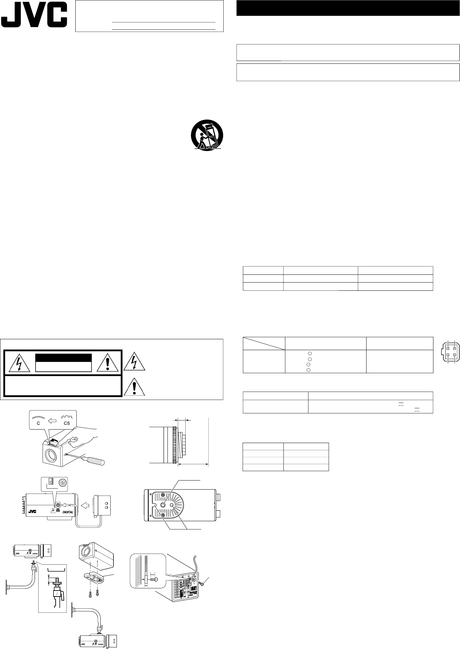
MOUNTING A LENS
1. Before mounting a lens, check whether it is a C-mount or CS-mount lens.
If a C-Mount lens is used, loosen the back-focus locking screw (M 2.6) using a Phillips
head screwdriver, turn the back-focus adjusting ring with your fingers or the screw-
driver and change the mounting method.
2. Dimension (b) of the lens shown in the illustration must be as shown in the table
below. If (b) exceeds the value in the table, it may damage the inside of the camera
or correct mounting may be impossible; never use such lenses. Do not attach the C-
mount lens when using a CS-mount.
The F mark indicates a focal point.
3. Mount the lens on the camera by turning the lens clockwise. Adjust its position.
4. When using an auto-iris lens with an EE amplifier, turn the switch to the
“VIDEO”
side. When no EE amplifier is equipped, turn the switch to the
“DC” side.
5. If the lens has an auto-iris mechanism, connect the lens cable after checking the pin
arrangement.
If the lens cable has a different type of plug, use the 4PIN PLUG supplied.
CONNECTION
1. When the camera is powered, the POWER LED lights up.
• Never connect the DC 12V and AC 24V power inputs simultaneously.
• Be sure to observe the correct +,
– polarity when connecting a DC 12V power input.
2. Connect the VIDEO OUT +/- terminals, which are on the rear panel, to the +/- terminals
on the receiver using twisted pair cable.
3. MONITOR Terminal
The MONITOR Terminal is for connecting to a video monitor. The MONITOR Termi-
nal is used for adjustment of screen framing.
*The VIDEO OUT and MONITOR Terminal cannot be used simultaneously.
4. When mounting the camera on a fixer, pan/tilt, etc., use the camera mounting screw
hole (d) located on the camera-mounting bracket.
CAUTION: Use the screw with a length shorter than 7mm from a camera-mount-
ing face.
Furthermore, make use of the rotation prevention hole (e) to prevent the camera
from falling and securely mount the camera.
Special precautions must be taken for mounting the camera on a wall or a ceiling.
We are not liable for any damage caused by improper installation.
5. Installation of camera
• Mounting from the bottom
This camera is originally designed to be mounted from the bottom, as shown q.
The hole is standard photographic pan-head screw size (1/4-20 UNC). Example
the Fixing unit or Pan/Tilt unit.
• Mounting from the top
Remove the CAMERA MOUNTING BRACKET (f) from the bottom of the camera by removing
two fixing screws as shown w. Attach the CAMERA MOUNTING BRACKET (f) to the top, then
mount the camera on the Fixing Unit as shown e. Make sure that two original screws are used
when mounting the CAMERA MOUNTING BRACKET (f). Be sure to use a 6 mm long locking
screw for the camera-mounting bracket.
(This camera is used indoor and under similar conditions.)
Fall Prevention
• Exercise maximum caution when installing the unit to the wall or ceiling. You should
not engage in the installation work yourself. Ask a professional to do the job, since
the fall of the unit can result in injuries and accidents.
• When installing the unit on a fixer, turn table, etc., make sure to install it firmly using
a rotation-preventing hole provided to prevent fall.
• To prevent fall, connect the unit to a section with sufficient strength (ceiling slab or channel)
using a fall prevention wire such as a wire chain and the like. Use the screw hole on the back of
the unit for installation.
Pay utmost attention to the length of the wire, too.
• Specified screw (M3 × 6 mm)
Be sure to attach the fall prevention wire by securing it with the screw that is provided
for that purpose on the rear panel.
1
3
4
2
∆A
∆B
∆C
∆D
∆E
∆F
CAMERA type power
TK-C720TPU AC 24V ` (class 2 only) or DC 12V
TK-C720TPE AC 24V ` (isolated power only) or DC12V
Manufacturer Model No.
NITEK VB37
NVT NV-213A
NVT NV-652R
*Recommended Receiver •Recommended wires
•
Unshielded Twisted Pair
•
Wire gauge 0.5mm (24AWG) or Thicker
•
Category Type: 5
* When using twisted pair cable, make sure that the
+/- polarities are correct.