


1. Read all of these instructions.
2. Save these instructions for later use.
3. All warnings on the product and in the operating instructions should be adhered to.
4. Unplug this appliance system from the wall outlet before cleaning. Do not use liquid cleaners or aerosol cleaners.
Use a damp cloth for cleaning.
5. Do not use attachments not recommended by the appliance manufacturer as they may cause hazards.
6. Do not use this appliance near water - for example, near a bathtub, washbowl, kitchen sink, or laundry tub, in a wet
basement, or near a swimming pool, etc.
7. Do not place this appliance on an unstable cart, stand, or table. The appliance may fall,
causing serious injury to a child or adult, and serious damage to the appliance may fall,
causing serious injury to a child or adult, and serious damage to the appliance.
Use only with a cart or stand recommended by the manufacturer, or sold with the appliance.
Wall or shelf mounting should follow the manufacturer’s instructions, and should use a mounting
kit approved by the manufacturer.
An appliance and cart combination should be moved with care. Quick stops, excessive force,
and uneven surfaces may cause the appliance and cart combination to overturn.
8. Slots and openings in the cabinet and the back or bottom are provided for ventilation, and to
insure reliable operation of the appliance and to protect it from overheating, these openings
must not be blocked or covered. The openings should never be blocked by placing the appliance on a bed, sofa,
rug, or other similar surface. This appliance should never be placed near or over a radiator or heat register. This
appliance should not be placed in a built-in installation such as a bookcase unless proper ventilation is provided.
9. This appliance should be operated only from the type of power source indicated on the marking label. If you are
not sure of the type of power supplied to your home, consult your dealer or local power company. For appliance
designed to operate from battery power, refer to the operating instructions.
10. This appliance system is equipped with a 3-wire grounding type plug (a plug having a third (grounding) pin). This
plug will only fit into a grounding-type power outlet. This is a safety feature. If you are unable to insert the plug into
the outlet, contact your electrician to replace your obsolete outlet. Do not defeat the safety purpose of the grounding
plug.
11. For added protection for this product during a lightning storm, or when it is left unattended and unused for long
periods of time, unplug it from the wall outlet and disconnect the antenna or cable system. This will prevent
damage to the product due to lightning and power-line surges.
12. Do not allow anything to rest on the power cord. Do not locate this appliance where the cord will be abused by
persons walking on it.
13. Follow all warnings and instructions marked on the appliance.
14. Do not overload wall outlets and extension cords as this can result in fire or electric shock.
15. Never push objects of any kind into his appliance through cabinet slots as they mat touch dangerous voltage
points or short out parts that could result in a fire or electric shock. Never spill liquid of any kind on the appliance.
16. Do not attempt to service this appliance yourself as opening or removing covers may expose you to dangerous
voltage or other hazards. Refer all servicing to qualified service personnel.
17. Unplug his appliance from the wall outlet and refer servicing to qualified service personnel under following conditions:
a. When the power cord or plug is damaged or frayed.
b. If liquid has been spilled into the appliance.
c. If the appliance has been exposed to rain or water.
d. If the appliance does not operate normally by following the operating instructions. Adjust only those controls that
are covered by the operating instructions as improper adjustment of other controls may result in damage and
will often require extensive work by a qualified technician to restore the appliance to normal operation.
e. If the appliance has been dropped or the cabinet has been damaged.
f. When the appliance exhibits a distinct change in performance - this indicates a need for service.
18. When replacement parts are required, be sure the service technician has used replacement parts specified by the
manufacturer that have the same characteristics as the original part. Unauthorized substitutions may result in fire,
electric shock, or other hazards.
19. Upon completion of any service or repairs to this appliance, ask the service technician to perform routine safety
checks to determine that the appliance is in safe operating condition.
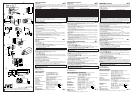
TK-C700/ TK-C720
These instructions are for TK-C700U, TK-C720U, TK-C700E and TK-C720E.
Objectif Diaphragme CC Diaphragme VIDEO
No. de broche
(sans amplificateur EE) (avec amplificateur EE)
1 Frein
–
9,5 V [50 mA max]
2 Frein
+
NC
3 Tournevis
+
VIDEO
4 Tournevis
–
Terre
Information for USA
This device complies with Part 15 of the FCC Rules.
Changes or modifications not approved by JVC could void the user’s authority to operate the equipment.
Lens Flange back (c) Dimension (b)
C mount lens 17.526mm 10mm or less
CS mount lens 12.5mm 5.5mm or less
Lens DC IRIS VIDEO IRIS
Pin No. (does not contain EE amplifier) (contain EE amplifier)
1Brake
–
9.5V [max 50mA]
2Brake
+
NC
3Drive
+
VIDEO
4Drive
–
GND
CAMERA type power
TK-C700U/TK-C720U AC 24V
~
(class 2 only) or DC 12V
TK-C700E/TK-C720E AC 24V
~
(isolated power only) or DC12V
Objetivo Reborde (c) Dimensión (b)
Objetivo de montura C 17,526 mm 10 mm o menos
Objetivo de montura CS 12,5 mm 5,5 mm o menos
Objetivo Iris DC Iris VIDEO
Núm. de contacto
(No posee amplificador EE) (Posee amplificador EE)
1 Freno
–
9,5 V [50 mA como máx.]
2 Freno
+
Sin conexión
3 Excitación
+
VIDEO
4 Excitación
–
Masa
Tipo de videocámara Alimentación
TK-C700U/TK-C720U
24 V CA
~
(clase 2 solamente) o 12 V CC
TK-C700E/TK-C720E
24 V CA
~
(alimentación aislada solamente)
o12 V CC
For Customer Use:
Enter below the Serial No. which is located on the body.
Retain this information for future reference.
Model No.
Serial No.
Type de CAMERA Alimentation
TK-C700U/TK-C720U CA 24 V
~
(classe 2 uniquement) ou CC 12 V
TK-C700E/TK-C720E CA 24 V
~
(
alimentation isolée uniquement) ou CC12V
Objectif Foyer arrière (c) Dimension (b)
Objectif à monture C 17,526 mm 10 mm ou moins
Objectif à monture CS 12,5 mm 5,5 mm ou moins
®
The lightning flash with arrowhead symbol, within an equi-lateral triangle, is intended to alert the
user to the presence of uninsulated “dangerous voltage” within the product’s enclosure that may
be of sufficient magnitude to constitute a risk of electric shock to persons.
The exclamation point within an equilateral triangle is intended to alert the user to the presence of
important operating and maintenance (servicing) instructions in the literature accompanying the
appliance.
For USA and CANADA
CAUTION: TO REDUCE THE RISK OF ELECTRIC SHOCK.
DO NOT REMOVE COVER (OR BACK).
NO USER SERVICEABLE PARTS INSIDE.
REFER SERVICING TO QUALIFIED SERVICE PERSONNEL.
CAUTION
RISK OF ELECTRIC SHOCK
DO NOT OPEN
INFORMATION (FOR CANADA) RENSEIGNEMENT (POUR LE CANADA)
This Class [B] digital apparatus complies with Canadian ICES-003.
Cet appareil numérique de la classe [B] est conforme à la norme NMB-003 du Canada.
IMPORTANT SAFEGUARDS
1
3
4
2
1
3
4
2
1
3
4
2
PORTABLE CART WARNING
(symbol provided by RETAC)
S3126A
COLOR VIDEO CAMERA Instructions
Thank you for purchasing the JVC color video camera.
To obtain the best results from your new camera, read these instructions carefully before use;
retain the manual for future reference.
WARNING:
TO PREVENT FIRE OR SHOCK HAZARD, DO NOT EXPOSE THIS UNIT TO RAIN OR MOIS-
TURE.
Due to design modification, data given in this instruction book are subject to possible change
without prior notice.
PRECAUTIONS
• If an AGC switch is turned on, the sensitivity increases automatically in dark places. It is not a
failure when the image looks grainy.
• If a zoom lens is used, check the back focus before mounting the camera. This also applies to
lens ALC and LEVEL. (See the instructions on lenses for details.)
• If a high-intensity object (such as a lamp) is shot, the image on the screen may have vertical
lines (smear) or blur (blooming) at its periphery (especially in AES mode). This is a characteristic
of the CCD, and is not a defect.
• If an EE lens is used, set the automatic electronic shutter switch (AES) to OFF. If set to ON,
flickering may occur. If a manual iris lens is used, set the AES to ON.
• When used in hot places, vertical lines may appear on the screen of this camera. This is a
characteristic of the CCD and not a failure of the camera.
• The automatic tracking system may not function properly when shooting with non-standard
lighting or lighting with a color temperature which exceeds the capability of the camera. In such
a case, set to the “MANU” position.
• If the camera subject is a single solid color (other than white), the auto white circuit will normally
attempt to change this color to white. In the case of this camera, if it cannot make a correct
prediction, the previous white balance setting will be maintained until the subject colors become
more varied.
• Where there are strong electromagnetic waves or magnetism, for example near a radio or TV
transmitter, transformer, motor, etc., the picture may contain noise and the colors may be incorrect.
• To save energy, be sure to turn off the system when not in use.
MOUNTING A LENS
1. Before mounting a lens, check whether it is a C-mount or CS-mount lens.
If a C-Mount lens is used, loosen the back-focus locking screw (M 2.6) using a Phillips
head screwdriver, turn the back-focus adjusting ring with your fingers or the screw-
driver and change the mounting method.
2. Dimension (b) of the lens shown in the illustration must be as shown in the table
below. If (b) exceeds the value in the table, it may damage the inside of the camera
or correct mounting may be impossible; never use such lenses. Do not attach the C-
mount lens when using a CS-mount.
The F mark indicates a focal point.
3. Mount the lens on the camera by turning the lens clockwise. Adjust its position.
4. When using an auto-iris lens with an EE amplifier, turn the switch to the “VIDEO”
side. When no EE amplifier is equipped, turn the switch to the “DC” side.
5. If the lens has an auto-iris mechanism,
Connect the lens cable after checking the pin arrangement.
If the lens cable has a different type of plug, use the 4-P plug supplied.
CONNECTION
1. When the camera is powered, the POWER LED lights up.
• Never connect the DC 12V and AC 24V power inputs simultaneously.
• Be sure to observe the correct +, – polarity when connecting a DC 12V power input.
2. Connect to a video monitor, etc. (75Ω)
3. To install the camera onto a tripod, fixing unit, or pan/tilt unit, use the fall-preventive
socket (d) shown in the illustration.
Special precautions must be taken for mounting the camera on a wall or a ceiling.
We are not liable for any damage caused by improper installation.
4. Installation of camera
• Mounting from the bottom
This camera is originally designed to be mounted from the bottom, as shown q.
The hole is standard photographic pan-head screw size (1/4-20 UNC). Example
the Fixing unit or Pan/Tilt unit.
• Mounting from the top
Remove the CAMERA MOUNTING BRACKET (e) from the bottom of the camera by removing
two fixing screws as shown w. Attach the CAMERA MOUNTING BRACKET (e) to the top,
then mount the camera on the Fixing Unit as shown e. Make sure that two original screws are
used when mounting the CAMERA MOUNTING BRACKET (e); longer type screws (over 5mm)
may damage inner components.
(This camera is used indoor and under similar conditions.)
Fall Prevention
• Exercise maximum caution when installing the unit to the wall or ceiling. You should
not engage in the installation work yourself. Ask a professional to do the job, since
the fall of the unit can result in injuries and accidents.
• When installing the unit on a fixer, turn table, etc., make sure to install it firmly using
a rotation-preventing hole provided to prevent fall.
• To prevent fall, connect the unit to a section with sufficient strength (ceiling slab or channel)
using a fall prevention wire such as a wire chain and the like. Use the screw hole on the back of
the unit for installation.
Pay utmost attention to the length of the wire, too.
• Specified screw (M3 × 6 mm)
Never use any screw longer than the specified length as the inside can be damaged.
CAMÉRA VIDÉO COULEUR Manuel d’instructions
Nous vous remercions d’avoir acheté cette caméra vidéo couleur JVC.
Pour obtenir les meilleurs résultats de votre nouvelle caméra, lisez attentivement ce manuel
d’instructions avant l’utilisation ; puis, conservez le manuel pour toute référence ultérieure.
Avertissement :
Pour éviter tout risque de choc électrique, ne pas exposer cet appareil à la pluie ni à l’humidité.
Pour des raisons d’évolution de la conception, le contenu de ce manuel d’instructions est sujet à
modification sans préavis.
PRÉCAUTIONS
• Si l’un des sélecteurs AGC est activé, la sensibilité augmente automatiquement dans les endroits
sombres. Si l’image présente un aspect granuleux, il ne s’agit pas d’une défaillance.
• Si l’on utilise un zoom, vérifier la mise au point arrière avant de monter la caméra. Ceci est
également valable pour le réglage ALC ou LEVEL de l’objectif. (Pour les détails, voir le manuel
d’instructions de l’objectif.)
• Lors de la prise de vue d’un sujet à forte intensité (par exemple une lampe), l’image de l’écran
risque de présenter des lignes verticales (estompage) ou un flou (flou d’image) sur son pourtour
(en particulier en mode AES). Ceci est typique des capteurs CCD et ne constitue pas une
défaillance.
• Si l’on utilise un objectif EE, régler le commutateur d’obturateur électronique automatique (AES)
sur OFF. S’il est réglé sur ON, il risque d’y avoir un phénomène de scintillement. Si l’on utilise un
objectif à diaphragme manuel, régler l’AES sur ON.
• Dans les endroits chauds, des lignes verticales peuvent apparaître sur l’écran de la caméra.
Ceci est typique des capteurs CCD et ne constitue pas une défaillance.
• Le système d’alignement automatique peut ne pas fonctionner correctement lors d’une prise de
vues avec un éclairage non standard ou un éclairage d’une température de couleur dépassant
la capacité de la caméra. Dans ce cas, régler sur la position “MANU”.
• Si le sujet de la prise de vues est une couleur pleine (autre que le blanc), le circuit automatique
du blanc tentera normalement de transformer cette couleur en blanc. Avec cette caméra, s’il
n’est pas possible d’effectuer un ajustement correct, le réglage précédent de la balance du
blanc sera conservé jusqu’à ce que les couleurs du sujet soient plus diversifiées.
• En présence d’ondes électromagnétiques ou de magnétisme puissant, par exemple près d’un
émetteur radio ou d’un téléviseur, d’un transformateur, d’un moteur, etc., l’image risque de
renfermer des parasites et les couleurs de ne pas être correctes.
• Pour économiser l’énergie, bien mettre le système hors tension lorsqu’on ne s’en sert pas.
MONTAGE D’UN OBJECTIF
1. Avant de monter l’objectif, vérifier s’il possède une monture C ou une monture CS.
Pour utiliser un objectif à monture C, desserrer la vis de verrouillage de mise au
point arrière (M 2,6) à l’aide d’un tournevis à tête Pillips, puis tourner la bague de
réglage de mise au point arrière avec les doigts ou avec le tournevis, et changer de
méthode de montage.
2. La dimension (b) de l’objectif indiquée sur le schéma doit être comme indiqué dans
le tableau ci-dessous. Si (b) dépasse la valeur du tableau, cela risque d’endommager
l’intérieur de la caméra ou d’empêcher un montage correct ; ne jamais utiliser ce
genre d’objectifs. Ne pas fixer d’objectif à monture C sur une monture CS.
L’indication F représente le foyer.
3. Monter l’objectif sur la caméra en tournant l’objectif dans le sens des aiguilles d’une
montre. Ajuster sa position.
4. Si l’objectif possède un mécanisme de diaphragme automatique avec amplificateur
EE, tourner le commutateur sur le côté “VIDEO”. Si l’objectif ne renferme pas
d’amplificateur EE, tourner le commutateur sur le côté “DC”.
5. Si l’objectif possède un diaphragme automatique,
Raccorder le câble d’objectif après avoir vérifié la disposition des broches.
Si le câble d’objectif possède une fiche de type différent, utiliser la fiche à 4 broches
fournie.
Raccordement
1. Quand la caméra est sous tension, le voyant POWER s’allume.
• Ne jamais raccorder simultanément les entrées d’alimentation CC 12 V et CA 24 V.
• Lors du raccordement d’une entrée d’alimentation CC 12 V, bien respecter les polarités + et –.
2. Raccorder à un moniteur vidéo, etc. (75 ohms).
3. Pour installer la caméra sur un pied, un module de fixation ou un module de
mouvement horizontal/vertical, utiliser la douille anti-chute (d) comme indiqué sur le
schéma.
Prendre des précautions spéciales si la caméra doit être montée sur un mur ou un
plafond. Nous ne saurions être tenus responsables des dommages résultant d’une
installation incorrecte.
4. Installation de la caméra
• Montage sur le fond
La caméra a été originellement conçue pour un montage sur le fond, comme indiqué
sur le schéma q. L’orifice respecte le format de vis photographique à tête à 6 pans
standard (1/4-20 UNC). Exemple : module de fixation ou module de mouvement
horizontal/vertical.
• Montage sur le dessus
Retirer le SOCLE DE MONTAGE DE LA CAMERA (e), sur le fond de la caméra, en enlevant
les deux vis de fixation comme indiqué sur le schéma w. Fixer le SOCLE DE MONTAGE DE
LA CAMERA (e) sur le dessus, puis fixer la caméra sur le module de fixation comme indiqué
sur le schéma e. Bien utiliser les deux vis d’origine pour monter le SOCLE DE MONTAGE DE
LA CAMERA (e); des vis plus longues (plus de 5 mm) pourraient endommager les composants
internes.
(La caméra est conçue pour une utilisation à l’intérieur ou dans des conditions similaires.)
Prévention des chutes
• Faire très attention lors de l’installation de l’appareil sur le mur ou au plafond. Ne pas
effectuer ce travail d’installation soi-même. Confier ce travail à un professionnel, car
la chute de l’appareil pourrait provoquer des blessures et des accidents.
• Si l’on installe l’appareil sur un support, une table rotative, etc., bien le fixer solidement
en utilisant l’un des orifices de prévention de rotation prévus pour l’empêcher de
tomber.
• Pour éviter toute chute, raccorder l’appareil à une section suffisamment résistante (dalle de
plafond ou cannelure) en utilisant un fil métallique de prévention des chutes, par exemple une
chaîne métallique. Pour l’installation, utiliser l’orifice de vis au dos de l’appareil.
Faire également extrêmement attention à la longueur du fil.
• Vis spécifiée (M3 × 6 mm)
Ne jamais utiliser de vis d’une longueur supérieure à la longueur spécifiée, car cela risque
d’endommager l’intérieur.
∆A
(See the
reverse side)
∆B
(See the
reverse side)
∆C
(See the
reverse side)
∆D
(See the
reverse side)
∆E
(See the
reverse side)
∆F
(See the
reverse side)
∆A
(Voir au verso.)
∆B
(Voir au verso.)
∆C
(Voir au verso.)
∆D
(Voir au verso.)
∆E
(Voir au verso.)
∆F
(Voir au verso.)
VIDEOCÁMARA EN COLOR Instrucciones
Muchas gracias por la adquisición de esta videocámara JVC.
Para obtener los mejores resultados de su nueva videocámara, antes de utilizar la videocámara,
lea cuidadosamente este manual de instrucciones, y consérvelo para futuras referencias.
ADVERTENCIA:
PARA EVITAR DESCARGAS ELÉCTRICAS, NO EXPONGA ESTA UNIDAD A LA LLUVIA NI A
LA HUMEDAD.
Debido a la modificación del diseño, los datos ofrecidos en este manual de instrucciones están
sujetos a cambio sin previo aviso.
PRECAUCIONES
• Si pone el interruptor AGC en ON, la sensibilidad aumentará automáticamente en lugares
obscuros. Cuando la imagen aparezca granulada, esto no significará mal funcionamiento.
• Si utiliza un objetivo para zoom, compruebe el enfoque antes de montar la videocámara. Esto
se aplica también al control automático del nivel (ALC) y al nivel (LEVEL) del objetivo. (Con
respecto a los detalles, consulte las instrucciones sobre los objetivos.)
• Cuando videofilme un motivo de gran intensidad (como una lámpara), la imagen de la pantalla
puede tener líneas verticales (borrosidad) o desenfoque (hiperluminosidad del punto explorador)
en su periferia (especialmente en el modo de obturador electrónico automático (AES). Ésta es
una característica del dispositivo de transferencia de carga (CCD), y no significa defecto alguno.
• Si utiliza un objetivo EE, ponga el interruptor del obturador electrónico automático (AES) en
OFF. Si lo pusiese en ON podría producirse parpadeo. Si utiliza un objetivo de iris manual,
ponga AES en ON.
• Cuando utilice la videocámara en lugares cálidos, es posible que aparezcan rayas verticales en
la pantalla de la misma. Esta es una característica del dispositivo de transferencia de carga
(CCD), y no significa defecto alguno.
• El sistema de seguimiento automático puede no funcionar adecuadamente cuando videofilme
en condiciones de iluminación no estándar, o con iluminación con una temperatura de color que
sobrepase la capacidad de la videocámara. En tal caso ajústelo a la posición “MANU”.
• Si somete la videocámara a un solo color (que no sea el blanco), el circuito de equilibrio
automático del blanco intentará normalmente cambiar este color al blanco. En el caso de esta
videocámara, si no puede realizar una predicción correcta, se mantendrá el ajuste del equilibrio
del blanco anterior hasta que los colores se vuelvan más variados.
• Cuando haya ondas electromagnéticas o campos magnéticos intensos, por ejemplo cerca de
un transmisor de radio o televisión, un transformador, un motor, etc., las imágenes pueden
contener ruido y los colores pueden ser incorrectos.
• Para ahorrar energía, asegúrese de apagar el sistema cuando no esté en uso.
MONTAJE DE UN OBJETIVO
1.
Antes de montar un objetivo, compruebe si la montura del mismo es de tipo C o CS.
Si se utiliza un objetivo con montura C, afloje el tornillo de fijación de retrofoco (M
2.6) con un destornillador de cabeza Phillips, y gire el anillo de ajuste de retrofoco
con sus dedos o el destornillador para cambiar el método de montaje.
2. La dimensión (b) del objetivo mostrado en la ilustración deberá ser como se indica en
la tabla siguiente. Si (b) sobrepasa el valor de la tabla, es posible que se dañe el
interior de la videocámara o que el montaje correcto resulte imposible. No utilice nunca
estos objetivos. No instale un objetivo de montura C cuando utilice una montura CS.
La marca F indica el punto focal.
3. Monte el objetivo en la videocámara girándolo hacia la derecha. Ajuste su posición.
4. Cuando utilice un objetivo de iris automático con amplificador EE, ponga el selector
en el lado “VIDEO”. Cuando el objetivo no disponga de amplificador EE, ponga el
selector en el lado “DC”.
5. Si el objetivo no dispone de mecanismo de iris automático, conecte el cable del
objetivo después de haber comprobado la disposición de los contactos.
Si el cable posee un tipo de conector diferente, utilice el conector de 4 contactos
suministrado.
CONEXIÓN
1. Cuando conecte la alimentación de la videocámara, se encenderá el LED POWER.
• No conecte nunca simultáneamente las entradas de alimentación de 12 V CC y 24 V CC.
• Tenga en cuenta la polaridad + y – cuando conecte la entrada de alimentación de 12 V CC.
2. Conecte a un videomonitor, etc. (75 ohmios)
3. Para instalar la videocámara en un trípode, unidad de fijación, o unidad de
panoramización horizontal/vertical, utilice un receptáculo contra caídas (d) como se
muestra en la ilustración.
Tome precauciones especiales cuando monte la videocámara en una pared o en el
techo. Nosotros no nos haremos responsables de los daños causados por la
instalación inadecuada.
4. Instalación de la videocámara
• Montaje desde la parte inferior
Esta videocámara ha sido originalmente diseñada para montarse desde la parte
inferior, como se muestra en q. El orificio roscado es de tamaño estándar de
cámaras fotográficas (1/4-20 UNC). Ejemplo de montaje de una unidad de fijación
o una unidad de panoramización horizontal/vertical.
• Montaje desde la parte superior
Quite el SOPORTE DE MONTAJE DE LA VIDEOCÁMARA (e) extrayendo los dos tornillos de
fijación, como se muestra en w. Fije el SOPORTE DE MONTAJE DE LA VIDEOCÁMARA (e)
en la parte superior, y después monte la videocámara en la unidad de fijación como se muestra
en e. Cerciórese de utilizar los dos tornillos originales cuando instale el SOPORTE DE
MONTAJE DE LA VIDEOCÁMARA (e), ya que si utilizase tornillos más largos (más de 5 mm)
podría dañar los componentes internos.
(Esta videocámara se utiliza en interiores y en condiciones similares.)
Prevención de caídas
• Preste suma atención cuando instale la unidad en la pared o el techo. No intente
realizar la instalación por su cuenta. Deje esta tarea en manos de un técnico, ya que
la caída de la unidad puede producir lesiones y accidentes.
• Cuando instale la unidad en un soporte de fijación, mesa giratoria, etc., asegúrese
de instalarla firmemente utilizando el orificio de prevención contra rotación provisto
para evitar las caídas.
• Para evitar caídas, conecte la unidad a una sección suficientemente resistente (bloque o
acanaladura del techo) utilizando un alambre rígido como una cadena metálica o similar. Para
la instalación, utilice el orificio roscado de la parte posterior de la unidad.
También preste suma atención al largo del alambre.
• Tornillo especificado (M3 × 6 mm)
Para evitar daños interiores, no utilice jamás un tornillo de un largo mayor que el especificado.
∆A
(
Véase el dorso)
∆B
(
Véase el dorso)
∆C
(Véase el dorso)
∆D
(Véase el dorso)
∆E
(Véase el dorso)
∆F
(Véase el dorso)