


16
Others
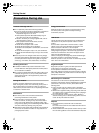
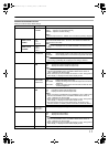
Ⅵ Items that must be set at the camera
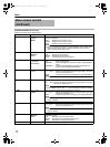
Ⅵ Items with restricted operation at VF-HP840U depending on camera settings
*1 The above feature may not function depending on the version of the camera’s software. For details, please consult JVC’s
authorized dealers.
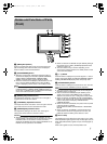
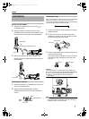
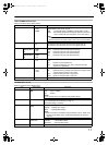
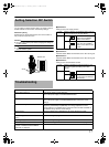
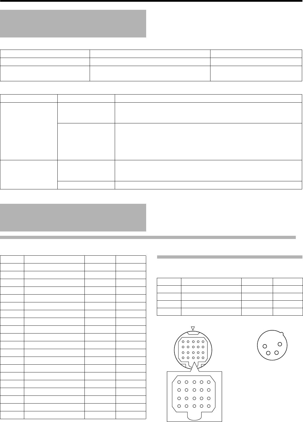
VF Terminal
20-pin Connector
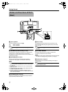
DC INPUT Terminal
4-pin Connector
Precautions when using
with GY-HD250U
Setting Item Setting ValueRemarks
VF SIGNAL Set to ARGBB or ACOMPONENTB
TALLY SYSTEM Set to ASTUDIOB Operation is also possible with
settings other than ASTUDIOB
*1
Setting Item Setting ValueRestricted Operation
VF SIGNAL RGB When the following functions are valid under GY-HD250U setting, the settings in
this product will be invalid.
*1
SAFETY ZONE, ZEBRA, FOCUS ASSIST, BLACK & WHITE
COMPONENT When the following functions are valid under GY-HD250U setting, the settings in
this product will be invalid.
ZEBRA
When connected to GY-HD250U, SKIN COLOR ADJUST screen displayed from
camera cannot be adjusted via this unit. When adjustment is requ ired, adjust via
the camera.
TALLY SYSTEM STUDIO The TALLY lamp displays TALLY(PGM/PVM), CALL and warning from the
remote control.
*1
Other than STUDIO The TALLY lamp displays the VTR operation status and warning.
Terminal Specifications
Pin No. Name Level IN/OUT
1 B/Pb 1 Vp-p IN
2GND ^^
3 +12 V +12 V IN
4GND ^^
5 VF ON/OFF +12 V IN
6 G/Y 1 Vp-p IN
7GND ^^
8 RM TALLY +3 V IN
9 RM PREVIEW TALLY +3 V IN
10 SDATA OUT +3 V OUT
11 R/Pr 1 Vp-p IN
12 GND ^^
13 SCLK +3 V IN
14 SDATA IN +3 V IN
15 SCS +3 V IN
16 +12 V +12 V IN
17 GND ^^
18 NC ^^
19 COM.DET 0 V IN
20 NC ^^
Pin No. Name Level IN/OUT
1GND ^^
2NC ^^
3NC ^^
4 +12 V +12 V IN
3
4
5
2
1
8
910
7
6
13 14 1512
11
18 19 2017
16
1
2
3
4
3
4
5
2
1
8
910
7
6
13
14
15
12
11
18
19
20
17
16
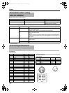
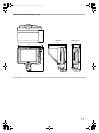
[VF CABLE] connector [DC INPUT] connector
VF-HP840U_EN.book Page 16 Thursday, January 17, 2008 2:48 PM