18 Pelco Manual C538M-A (3/04)
4.3 DAISY-CHAINING
Daisy-chaining occurs when more than 64 relays are required.
More importantly, each unit must be configured to have a unique address, referred
to as a Frame Address. Frame addressing with respect to REL units was discussed
in Section 3.3.1. What follows is a discussion about the physical hook-up of multiple
REL units. System software supports up to 700 GPIs or 5,600 relays. Whether
daisy-chaining two or multiple REL units, the first unit is connected from its “IN”
connector to the CC1 and connected to the second unit through its “OUT” connec-
tor. Subsequent units are chained together in the same way.
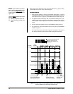
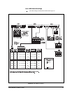
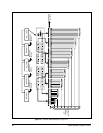
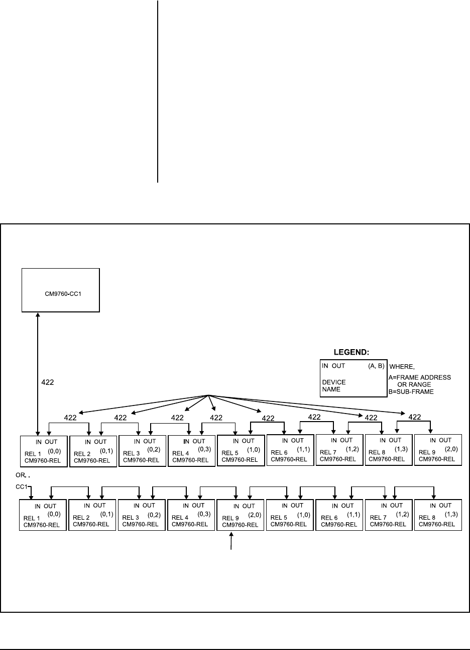
Figure 14 illustrates the physical hook-up of two cascaded configurations, each
containing nine REL units having the frame addresses illustrated in Figure 9.
Note that the physical order that any unit has in the configuration is independent of
its frame/sub-frame address.
Also note that the remarks made in the previous section regarding RS-422 wiring
run distances applies here when considering cables distance runs between daisy-
chained units.
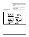
Figure 14. Relay Unit Daisy-Chain Configuration
NOTE:
Since VCRC units also uti-
lize GPI addressing, they can be
bussed together with REL units.
THE DIAGRAM BELOW DEPICTS VALID PHYSICAL HOOKUP VARIATIONS
OF THE SETUP DISCUSSED IN FIGURE 9 (MANY OTHERS ARE POSSIBLE).
SINCE EACH UNIT HAS A UNIQUE ADDRESS, IT MAKES NO DIFFERENCE
WHERE, IN THE CASCADED CHAIN, A PARTICULAR UNIT IS LOCATED.
HOOK-UP (1) AND (2) BELOW DIFFER PHYSICALLY, BUT ARE OPERATIONALLY
THE SAME (SEE NOTE).
(1)
(2)
NOTE: PHYSICAL LOCATION OF REL 9 IN (2) IS DIFFERENT THAN REL 9 IN (1),
BUT OPERATIONALLY THE SAME BECAUSE THE FRAME ADDRESS HAS
NOT CHANGED.
SWAPPED OR REVERSE CABLES
(REFER TO SECTION ON COMMUNICATION CONNECTORS)


