C1640M-B (3/06) 25
MANAGED NETWORK CONFIGURATION
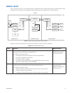
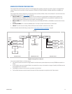
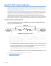
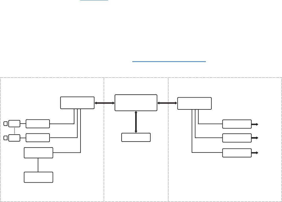
The managed Endura network supports viewing of live and playback video, recording, and security. As shown in Figure 9, a managed Endura
network includes the full assortment of Endura components: NET5301Ts, NET5301Rs, WS5050s, VCD5000s, NVR5100s, the SM5000, and
switches.
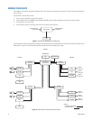
The managed Endura network is designed in a four-part block structure (A Block, B Block, C Block, and Core Block). For more information about
the block design concept, refer to Endura C Block on page 23.
• A Block (VLAN 2): This is where all video streams enter the network (both live and playback) and where video is recorded by the
NVR5100s and stored in SEB5000s. Each A Block can contain no more than 48 NET5301Ts and one NVR5100. The NVR5100 in each
respective A Block records video steams from the Encoders in the same A Block.
• B Block (VLAN 4): This is where all video viewing takes place, and VCD5000s, NET5301Rs, and WS5050s are connected to the Endura
network.
• Core Block (VLAN 3): This is where the SM5000 resides. The Endura Core Block interconnects the A and B Blocks.
• C Block: The entire structure including A Blocks, B Blocks and the Core Block is referred to as the C Block.
For more information about the block design concept, refer to Endura Network Design Considerations on page 8.
Figure 9. Managed Endura Network
You can have multiple A Blocks in an Endura network.
• The number of cameras and amount of storage needed for the video security network determines how many SEB5000s are needed in an
A Block.
• As with A Blocks, there can be multiple B Blocks in the network, but as many as the network can support. Generally, the B Block uses the
most bandwidth across the network.
• The SM5000 is connected to the core switch and resides in the Core Block.
• The Core Block implements network connectivity between all Endura components to comprise the basic Endura network.
A BLOCK-VLAN 3 CORE BLOCK-VLAN 2
C BLOCK
SM5000
NVR
SEB
ENCODER
ENCODER
VLAN 3
VLAN 3
VLAN 3
VCD
WS
DECODER
VLAN 4
VLAN 4
VLAN 4
VLAN 3 VLAN 4
B BLOCK-VLAN 4
CAMERA
VIDEO IN
A BLOCK
LAYER 2 SWITCH
CORE BLOCK
LAYER 3 SWITCH
B BLOCK
LAYER 2 SWITCH
DISPLAY
VIDEO OUT
DISPLAY
VIDEO OUT
DISPLAY
VIDEO OUT
VLAN 2


