C2403M-C (10/05) 7
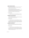
WIRING THROUGH SIDE CONDUIT
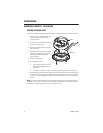
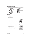
Follow the proceeding steps when feeding wire/cables through the side conduit opening of the unit:
1. Attach the cover to the mounting surface (hardware not supplied). Use stainless steel
hardware when installing the system outdoors.
2. Remove the conduit plug from the side of the back box.
3. Use a blunt tool to pull the wires and plug, located on the base of the back box into the back
box. Insert the black plug (supplied) into the hole in the base of the back box.
4. Install the back box inside the cover. Rotate and position the back box so that the conduit hole
on the side of the back box is aligned with the side notch of the cover. Use the supplied
8-32 x 0.375-inch screws and washers to secure the back box to the cover.
5. Install a 0.75-inch (1.91 cm) conduit fitting in the conduit hole of the back box.
6. Connect the video cable.
7. Connect the power wires.
• For 12 VDC, connect the 24 VAC/12 VDC (red) and GND (black) wires to input power.
• For 24 VAC, connect the 24 VAC/12 VDC (red) and 24 VAC (blue)wires to input power.
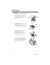
MOUNTING TO A 4S ELECTRICAL BOX
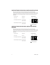
1. Attach the ICS110-AP adapter plate (not supplied) to a 4S box with the two 8-32 x 0.75-inch
flat head screws supplied with the adapter plate.
2. Pull the video and power wires into the cover, and then attach the cover to the adapter plate
with the three supplied 8-32 x 0.375-inch pan head screws.
3. Connect the video cable.
4. Connect the power wires.
• For 12 VDC, connect the 24 VAC/12 VDC (red) and GND (black) wires to input power.
• For 24 VAC, connect the 24 VAC/12 VDC (red) and 24 VAC (blue) wires to input power.
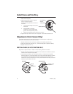
5. Install the back box inside the cover. For vandal-resistant installations, rotate and position the
back box so that the conduit plug on the side of the box is located on the opposite side (180
degrees) from the notch on the side of the cover. Use the supplied 8-32 x 0.375-inch screws
and washers to secure the back box to the cover.
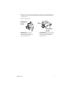
MOUNTING TO A PLASTER RING
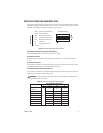
1. Pull video and power wires into the cover, and then attach the cover to a 404 plaster ring.
Use the two supplied 6-32 x 0.75-inch pan head screws to attach the cover to a 404 plaster
ring.
2. Connect the video cable.
3. Connect the power wires.
• For 12 VDC, connect the 24 VAC/12 VDC (red) and GND (black) wires to input power.
• For 24 VAC, connect the 24 VAC/12 VDC (red) and 24 VAC (blue) wires to input power.
4. Install the back box inside the cover. For vandal-resistant installations, rotate and position the
back box so that the conduit plug on the side of the box is located on the opposite side (180
degrees) from the notch on the side of the cover. Use the supplied 8-32 x 0.375-inch screws
and washers to secure the back box to the cover.


