Pelco Manual C1472M-C (10/05) 7
TROUBLESHOOTING
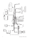
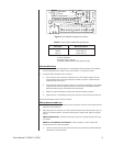
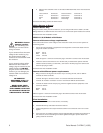
If you need to troubleshoot the circuit board or wiring, refer to Figure 1, HS4514 Series Input
Wiring Diagram, and Figure 2, Circuit Board Component Locations.
After the enclosure is mounted, opening the enclosure is more convenient using the following
procedure:
1. Remove the two tamper-resistant screws securing the front of the enclosure cover.
2. Loosen, but do not remove, the two tamper-resistant screws securing the rear of the
enclosure cover.
3. Push the top of the enclosure back approximately 1/4-inch (0.63 cm) and flip the top open.
Reverse the procedure to close.
MAINTENANCE
Regularly scheduled maintenance is not required. Clean the outer surface of the enclosure with
a nonabrasive cleaning cloth and antistatic cleaner. Clean the viewing window with a mild non-
abrasive soap and water to maintain picture clarity. Do not use kerosene or similar substances
that may damage the surface.
Service Manual
If you need to repair the camera enclosure, obtain a service manual in one of the following ways:
• Go to Pelco’s web site at ftp://www.pelco.com and find service manual C1472SM.
• Contact Pelco’s Literature Department and request service manual C1472SM.
SPECIFICATIONS
MECHANICAL
Camera Mounting: Removable camera sled that can be inverted to accommodate various
cameras and lenses
Maximum Camera
and Lens Size: Accepts camera and lens combinations (including BNC connector) up to:
HS4514 6.70 in. H x 5.25 in. W x 14.0 in. L (17.02 x 13.34 x 35.56 cm)
HS4514-1/-2/-3 6.25 in. H x 3.75 in. W x 12.0 in. L (15.88 x 9.53 x 30.48 cm)
Cable Entry: Two openings 0.875-inch (2.22 cm), will accept PG-13.5 watertight
fittings. Maximum cable diameter 0.47-inch (1.19 cm) or 1/2-inch
(1.27 cm) conduit fittings (fittings not provided.)
Lock: Four 1/4-20 tamper-resistant screws (#10 1/4-inch drive socket for
removing screws supplied; 1/4-inch drive tool not provided)
ELECTRICAL
Power Input: 24, 120, or 230 VAC; 50/60 Hz
Heater Power
Consumption: 120 VAC 24 VAC 230 VAC
HS4514-1/-2/-3 60 watts 50 watts 55 watts
Heater is thermostatically controlled to activate ON at 42°-58°F
(6°-14°C) and OFF at 72°-88°F (22°-31°C)
Electrical Connections: One each of the following:
3-pin connector terminal block for power input
6-pin lens connector
9-pin connector terminal block for lens wiring
10-pin connector terminal block for camera/lens wiring
2-pin connector terminal block for spare connections
3-pin socket for camera power input
2-pin socket for optional camera power input
4-pin socket for heaters


