C2961M (10/09) 5
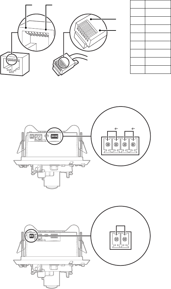
3. Plug the network cable into the RJ-45 network port on the side of the back box. If the network has
no PoE, connect a 24 VAC Class 2 power supply to the 24 VAC power connector.
Figure 3. RJ-45 Pin Descriptions
4. Connect the necessary wiring for alarms and relays (refer to Figure 4). Only use the 24 VAC wires if
PoE is not available.
Figure 4. Alarm and Relay Wiring
Figure 5. 24 VAC Wiring
1
2
3
4
5
6
7
8
8 7 6 5
4
3
2 1
1
2
3
4
5
6
7
8
1
2
3
4
5
6
7
8
8 7 6 5 4 3 2 1
8
8
1
1
Pin Function
1TX+
2TX–
3RX+
4 PoE 1-2
5 PoE 1-2
6 RX–
7 PoE 3-4
8 PoE 3-4
24V~
RELAY
R1
ALARM
A1
RELAY
R1
ALARM
A1
24V~


