


Pelco Manual C517M Rev C (6/92) 5
5.0 OPERATION AND SYSTEM TEST
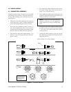
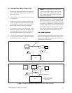
1. Hook up the control cable between the output con-
nector on MLZ6DT and the input connector on the
lens (see Figure 3).
2. Check that the video is connected from the camera
to the monitor.
3. Plug the mating connector of the wall mount trans-
former into the back of the MLZ6DT and plug the
transformer into a 120 VAC source. The power in-
dicator LED will light when power is applied.
4. For manual operation, put the switch in the
MANUAL position. Observing the monitor, test
for proper operation of zoom, focus, and iris func-
tions with related switches on the front panel.
5. Test for fast and slow speeds of all functions by
observing their operation as the LENS SPEED
knob on the front panel is adjusted.
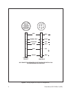
NOTE: AUTO operation only works in con-
junction with AI700 or AI701 auto iris servo
units. If the lens is equipped with AI700 or
AI701, use the following guidelines to test auto
operation (see Figure 4).
6. Connect the AI700 or AI701 as shown in Figure 4.
Put the power switch in the AUTO/ON position. The
IRIS switch should not operate; ZOOM and FO-
CUS switches should operate normally. Observing
the monitor, test operation of ZOOM and FOCUS
switches. Next, turn the lens toward a dark area, and
observing the monitor, check that the iris opens.
Move the lens back toward a lighter area, and ob-
serving the monitor, check that the iris closes.
6.0 MAINTENANCE
Under normal operating conditions and usage, mainte-
nance of this equipment is not necessary. However, if
maintenance should be required, consult Pelco or a
qualified service technician.
Figure 3. Basic System Configuration
Figure 4. System Configuration Using AI700 or AI701 Auto Iris Servo
COAX CABLE
CONTROL CABLE
MLZ6
WALL MOUNT
TRANSFORMER
CONTROL CABLE
MLZ6
WALL MOUNT
TRANSFORMER
A1700
COAX CABLE
(A1700 REQUIRES EXTERNAL
POWER SUPPLY)
AI700
(AI700 REQUIRES EXTERNAL
POWER SUPPLY)