


CAMERA Terms & Features
Video Security Systems
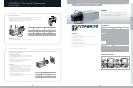
Lens Selection
When using an auto iris lens,
The lens selection switch next to the camera should be set according to the type of auto iris lens. Select ‘DC’ if the
installed lens is a DC-control type, and select ‘VIDEO’ if it is a video-control type.
Adjust the illumination level with the DC-IRIS VR at the back of the camera when DC-type is selected, or adjust the
Illumination level by using the level VR on the lens when video-type is selected.
* When using an AI lens,turn off the ELC switch at the back of the camera.
When using a manual iris lens,
Open the lens iris completely and turn on the ELC function at the back of the camera.
Rb
Pin3
Pin1
Pin2
Pin4
Pin no. DC Control Type VIDEO Control Type
1 Damp (-) Power (+12V)
2 Damp (+) N/A
3 Drive (-) VIDEO Signal
4 Drive (+) GROUND
Camera Back Focus Adjustment
The back focus of the camera is set when the product is shipped from the factory. However, the back focus can be adjusted in the following
manner if the focus is not properly set.
For Standard Lens (non-Zoom)
1. The lens should be able to clearly recognize high-definition images such as an
object with cross stripes from a distance of 10 meters when the focus ring of
the lens is set to infinity(∞).
2. Adjust the focus by turning the control ring of the flange back until the object
can be seen clearly under the circumstances described above.
3. Fasten the screw of flange back control ring.
For Zoom Lens
1. Place a high-definition image 3-5m apart from the camera and then turn the
focus of the lens as far as possible in the TELE (zoom in) direction so that the
image can be seen vividly as possible.
2. Turn the lens zoom as far as possible in the WIDE direction, turning the flange
back control ring of the camera so that the object can be seen most vividly.
3. Adjust so that the focus from the TELE side can be vividly matched with the
focus from the WIDE side by repeating above steps 1 and 2 2~3 times.
4. Fasten the screw of the flange back control ring.
The control can be set more accurately if the focus can be adjusted by attaching
dark color paper or ND filter to the front lens.
Flange Back Focusing Distance
C Mount 17.526mm
CS Mount 12.5mm
SCC-131B/101BP
1/3” High Resolution, Color Digital Camera
37
CAMERAS Video Security System
Features
Dimensions
(
unit:mm
)
• DSP (Digital Signal Processor)
• 1/3" Super HAD CCD (SCC-131B:410K/470K, SCC-131BP:470K)
• Horizontal resolution : 520 TV Lines
• Back light compensation circuitry
• External synchronization with Line lock
• Accepts 2 types of auto-iris lenses (DC / Video)
• Accepts CS/C-mount without adaptor
• Power input(SCC-101BP:AC220V~240V / SCC-131B(P):AC24V/DC12V)
• Built-in ground fault isolation transformer
Specifications
Summary
This color camera is capable of superb observation, thanks to its state-
of-the-art implementation of 1/3" CCD (410,000/470,000 pixels for
NTSC, 470,000 pixels for PAL) with economical price.
Imaging Device 1/3" Super HAD CCD
Effective Pixels 768(H)x494(V) 752(H)x582(V)
Scanning Method Interlace/Line lock
Scanning Horizontal 15.750Hz 15.625 Hz
Line Frequency Vertical 60Hz 50Hz
Synchronization Method Internal / Line lock (V PHASE control)
Horizontal Resolution 520 TV Lines
Video Output VBS 1.0Vp-p
S/N Ratio 50dB
Lens AI(Video/DC)
Minimum Scene Illumination 0.15(Sens up Off,15IRE)Lux
Functions BLC On
AGC On
White Balance ATW/AWC
ELC Off/On(Max. 1/120Ksec)
Operating Temperature -10°C ~ +50°C
Operating Humidity Less than 90%
Power Requirment AC24V/DC12V compatible
Power Consumption 3W
Weight 450g
Dimensions 65(W) x 52(H) x 133(D)mm
Model SCC-131B SCC-131BP
NEW PRODUCTS
CAMERAS
MONITORS DVRS NETWORK SECURITY CONTROLLERS
36
CAMERAS Video Security System
*
SCC-101BP is same as SCC-131BP except for Power Requirment (AC 220V~240V)
SCC-131B SCC-101BP