8
Chapter 1 Introduction
Features and Functions
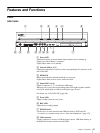
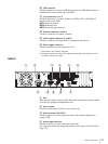
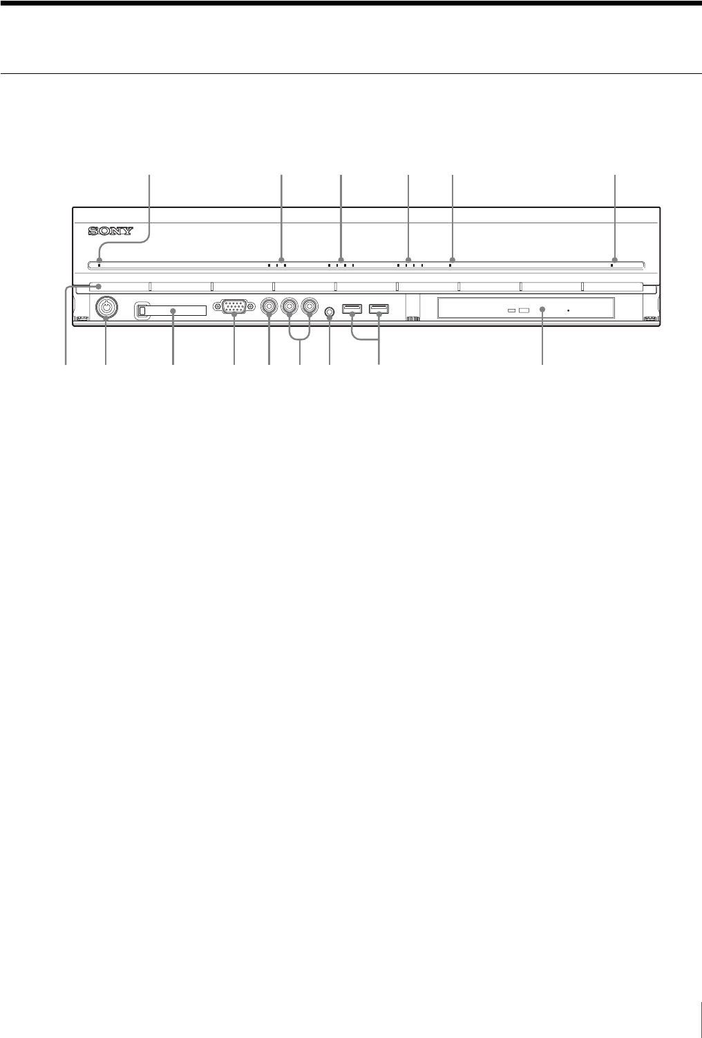
Front
NSR-100/50
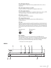
A Power LED
Alternates between green and amber lights when the unit is starting up.
Lights green when startup is complete.
Lights amber when it is on standby.
B Network LED (1 to 3)
Lights green when there is activity at the corresponding LAN connector at the
rear of the NSR.
C HDD LED
Blinks green when the internal hard disks are accessed.
Lights amber when an error occurs with a hard disk.
D Status LED (1 to 4)
Lights in sequence (1, 2, 3, 4) when the NSR starts.
When an error occurs, the corresponding status LED lights together with the
error LED, which lights or blinks to indicate the type of error.
For details, see “STATUS LED” (page 168).
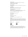
E Error LED
Lights or blinks when an error occurs.
F REC LED
Lights when recording images.
G DVD/CD drive
Use this drive to write data from the NSR hard disks to DVD and CD.
* For details on compatible media, refer to “Notes and Limitations” (page 173).
H USB connector
Use this connector to connect a USB keyboard, mouse, USB flash memory or
the RM-NS10 remote control unit to the NSR.
POWER 1 2 3NETWORK 1 2 3 4HDD 1 2 3 4 ERRORSTATUS REC
123 4 5 6
708q
a
9q
s
q
d
q
f
q
g


