


7
Chapter 7 Location and Function of Parts and Controls 140HDC-900/950/930 Series Product Information Manual
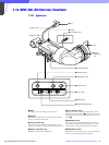
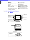
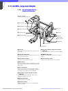
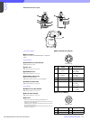
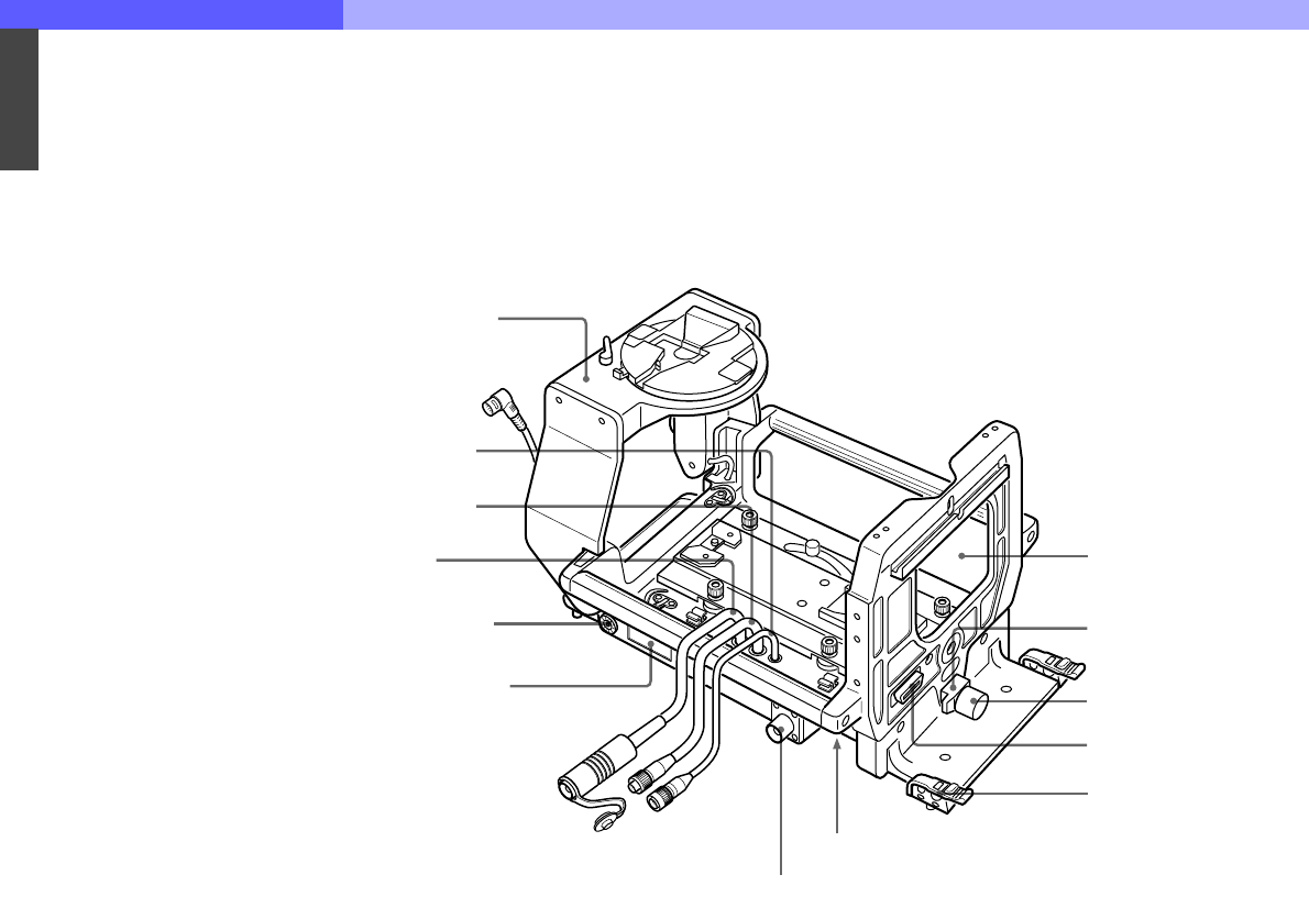
7-17. CA-905L, Large Lens Adaptor
7-17-1 Lens Attachment Section
(Front) and Connectors
a Lens lock
Secures the lens by the tongue-like protrusion at the
lens bottom.
b Lens lock holding knob
Secures the lens lock. Turn clockwise to tighten, and
counterclockwise to loosen.
c Lens connector (36-pin)
Connect to the connector on the lens.
d Cable clamp
Secures the camera cable. The diameter of the cable
with a diameter of 8 to 15 mm should be used with the
cable clamp.
e Lens mode switch
Selects one of the two lens communication modes.
During normal operation, set to NORMAL. During use
of a serial communication lens, set to SERIAL.
f CCU (camera control unit) fiber connector:
LEMO type
Connects through an optional fiber cable to the
CAMERA connector on the CCU.
g Number plate holder
Fit the supplied number plates.
h Accessory bracket
Attach an optional accessory, such as a BKP-7911/
7912 Script Holder.
i CA (camera adaptor) cable (fiber connector):
LEMO type
Connect to the CCU connector on the camera adaptor.
j REMOTE cable (8-pin)
Connect to the REMOTE connector on the camera
adaptor.
k Lens connector (12-pin)
Connect to the LENS connector of the camera.
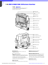
BKP-9057 Viewfinder
Saddle (not supplied)
qa Lens connector
1 Lens lock
2 Lens lock
holding knob
3 Lens connecto
r
4 Cable Clamp
Lens mouth
5 Lens mode switch
6 CCU connector
7 Number plate holder
8 Accessory bracket
9 CA cable
q; REMOTE cable