


120
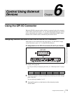
Using the GPI I/O Connector
Chapter 6 Control Using External Devices
For selectable functions, see “Functions enabled to be assigned to the pins
on the GPI I/O connector” on page 120.
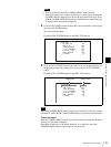
When you select “Button1” to “Button12” with the F2 control, the setting
item is displayed under “COLOR.” Turn the F3 control to select “Red” or
“Amber.”
The “Output” or “Input” indication is displayed under “I/O DIR” above the
F4 control depending on the selected function.
Output: to operate an external device using the control signal output from
the switcher
Input: to operate the switcher using the control signal input to the switcher
from an external device
Functions enabled to be assigned to the pins on the GPI I/O connector
NOP: Not used
Input
PGMBTN1 to PGMBTN12: PGM select buttons 1 to 12
NEXTBTN1 to NEXTBT12: NEXT select buttons 1 to 12
AUX1BTN1 to AUX1BT12, AUX1BTPG, AUX1BTPV, AUX1BTMV:
output signal selection with the AUX1 button
AUX2BTN1 to AUX2BT12, AUX2BTPG, AUX2BTPV, AUX2BTMV:
output signal selection with the AUX2 button
CUT: CUT button
ME AUTO: AUTO TRANS button
PIP AUTO: PIP AUTO button
DSK AUTO: DSK AUTO button
TRANSMIX: MIX button
TRANS WP: WIPE button
FRZ MEM1, FRZ MEM2: import of frame memory video 1, 2
CAM MODE: CAM mode button
SW MODE: SW mode button
DRCT-SS, DRCT-WP, DRCT-PIP: direct snapshot mode, direct wipe mode,
or direct PIP mode selection
DRCTRCL0 to DRCTRCL9: recall of DIRECT RECALL 0 to 9
Output
Button1 to Button12: Cross-point buttons (PGM select buttons and NEXT
select buttons) 1 to 12
DSK On: DSK AUTO button (On)
PIP On: PIP AUTO button (On)
CAM1 to CAM7: CAMERA 1 to 7 buttons
AUX1BTN1 to AUX1BT12, AUX1BTPG, AUX1BTPV, AUX1BTMV:
AUX 1 button
AUX2BTN1 to AUX2BT12, AUX2BTPG, AUX2BTPV, AUX2BTMV:
AUX 2 button
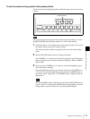
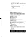
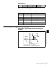
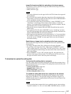
Setting example 1
If pin number 1 on the GPI I/O connector is connected to GND, the same
performance as that obtained by pressing the PGMBTN1 (PGM select button 1)
is executed.
UTILITY PIN NO FUNCTION COLOR I/O DIR 1/3
GPI
1 PGMBTN1 ----- Input 961