


137
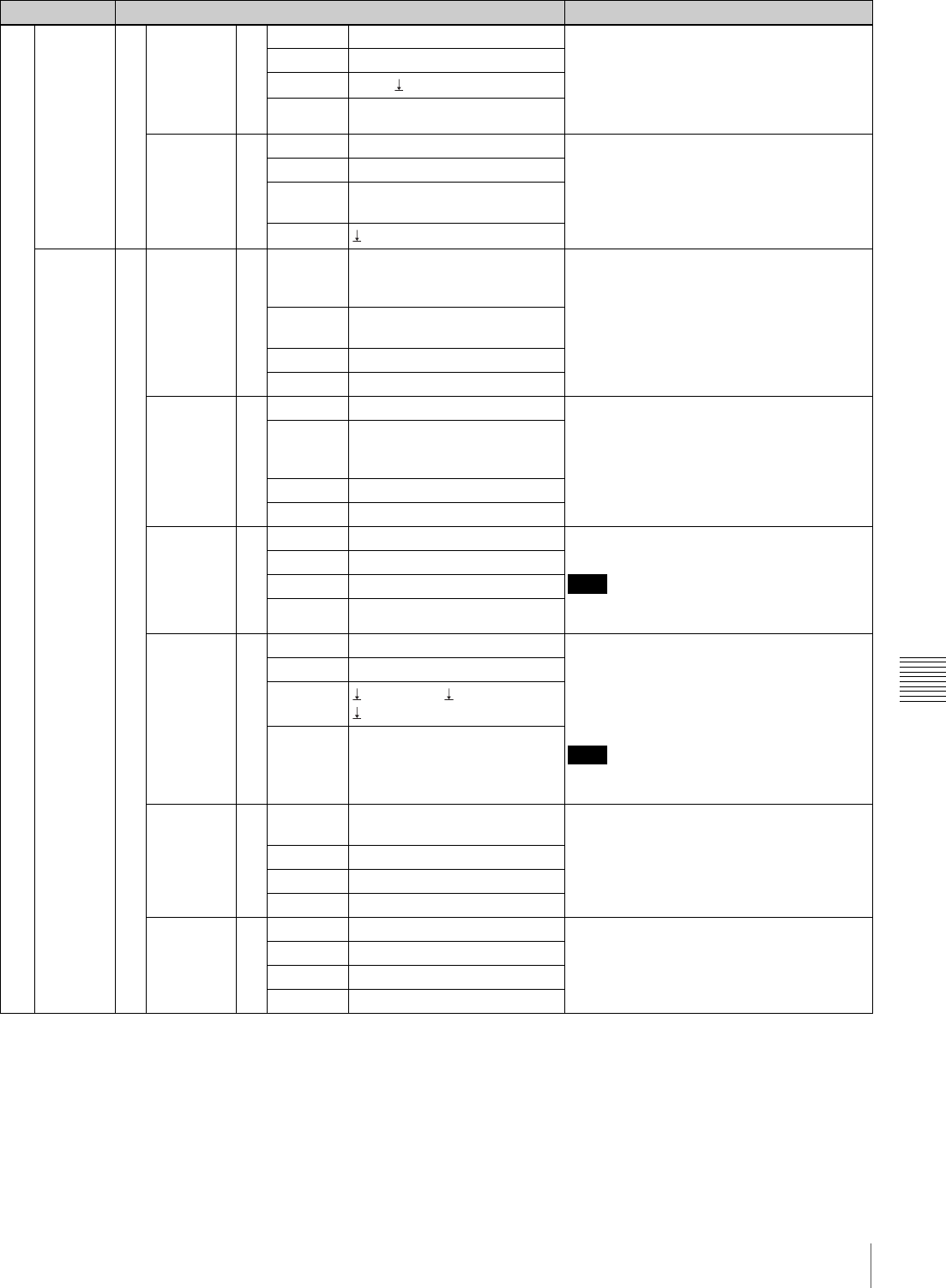
Menu List
Appendix
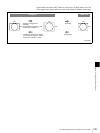
To register the name of the signal (menu page 921)
Each of the signals input from the connectors on the Processor Unit and frame memories, color mattes
and color bars built in the switcher can be named in four characters to register.
Open the menu page 921 and follow the procedure below:
1Turn the F1 or F2 control to select the signal to be registered.
2Press the F2 control to highlight a character.
3Turn the F2 control to change the highlighted character.
4Turn the F3 control to move the highlighting to the character to be changed.
When you move the highlighting to the space next to the fourth character on the right, the input
characters are registered.
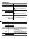
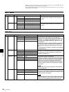
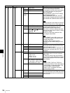
900 CAMERA.. 910 PWR MNG.. 917 CAM BTN All, 1 to 7 Sets power ON/OFF of the camera that
corresponds to the CAMERA button using
the F1 to F3 controls.
When AUTO ON is set to On, the power for
all the connected cameras is turned on in
conjunction with the switcher’s power.
TURN Off, On
APPLY
NOP, Exec
AUTO ON Off, On
PWRSTAT.. 918 CAM BTN 1 to 7 The power status of the camera that
corresponds to the CAMERA button is
displayed under STATUS when the F4
control is pressed.
NAME (4-character indication)
STATUS Sensing, On, Stand-By, Off,
Non Asgn (indication only)
CHECK
Exec
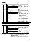
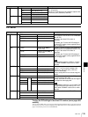
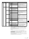
INPUT.. 920 NAME.. 921 SIGNAL IN 1, IN 2, IN 3, IN4, IN 5, IN 6,
IN 7, IN 8, IN 9, FM 1, FM 2,
MAT1, MAT2, CLBR
Allows you to register the name (in 4
characters) identifying each of the signals
input from the connectors on the Processor
Unit and frame memories, color mattes, and
color bars built in the switcher.
For details, see “To register the name of the
signal (menu page 921)” on page 137.
RENAME (4-character definition to be
input)
<=>
ASSIGN.. 922 XPT BTN 1 to 12 Assigns signals to the cross-point buttons.
Disables operation of the selected cross-
point button when INHIBIT is set to On.
SIGNAL IN 1, IN 2, IN 3, IN 4, IN 5, IN
6, IN 7, IN 8, IN 9, FM 1, FM 2,
MAT1, MAT2, CLBR
NAME (4-character indication)
INHIBIT Off, On
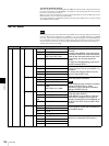
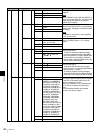
ADJUST.. 923 XPT BTN 1 to 12 Adjusts the levels of the signals that
correspond to the cross-point buttons.
Note
These adjustments are not available for DVI,
color matte, or frame memory signals.
Y-LEVEL 0.50 to 1.50 (1.00) (in 0.01)
SETUP –10.0 to 10.0 (0.0) (in 0.5)
C-LEVEL 0.50 to 1.50 (1.00) (in 0.01)
PROC.. 924 SIGNAL IN 5, IN 9 Sets the process of the aspect ratio of the
signal input from IN 5 or IN 9 when the
optional BRSA-20DD1 is installed.
For details, see “Conversion between Input
Signal and Output Signal” on page 142.
Note
These items can be set only when FORMAT
is set to HD on menu page 951.
NAME (4-character indication)
4:3 PROC
WidZoom, Center,
Zoom
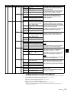
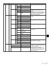
FS.. 925 SIGNAL SDI1, SDI2, SDI3, SDI4, SDI5,
SDI6, SDI7, SDI8
Allows you to add FS (frame synchronizer)
to the input signal selected under SIGNAL.
Set FS to On for the connected device to
which external sync signal cannot be added.
NAME (4-character indication)
FS Off, On
SIDE.. 926 LUM 0.0 to 100.0 (in 0.1) Sets color matte for the side cut area for an
available signal.
The F1 to F3 controls and the joystick can
be used for the setting.
SAT 0.0 to 100.0 (in 0.1)
HUE 0.0 to 359.5 (in 0.5)
Setting menu Setting item Description