


28
Control Panel
Chapter 2 Locations and Functions of Parts
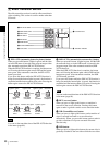
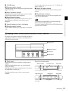
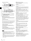
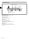
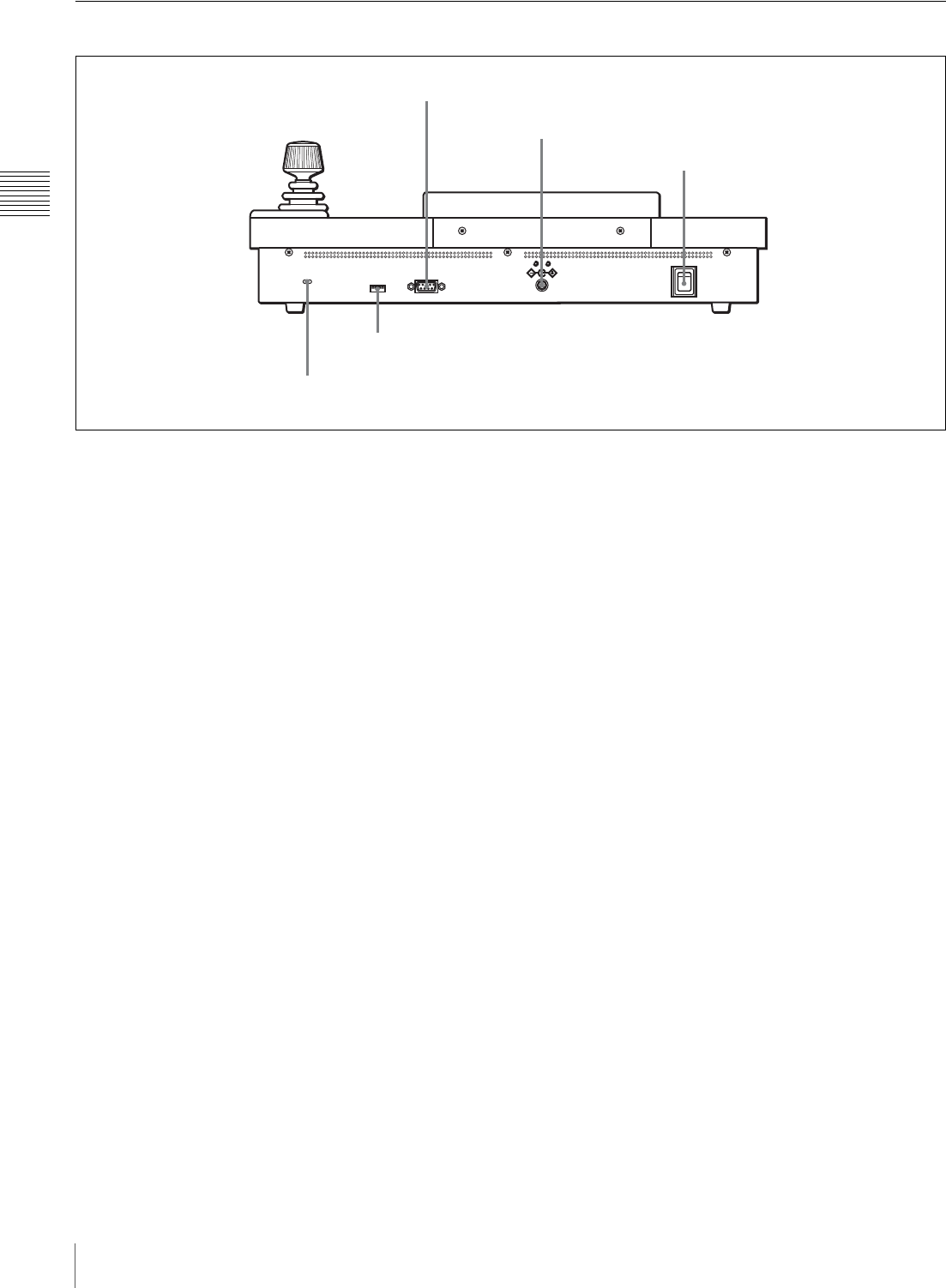
9 Rear Panel Section
a PROCESSOR connector
Connect to the PANEL connector on the Processor Unit
with the supplied control cable.
b DC IN 12V connector
Connect the supplied AC power adaptor.
c Power switch
Turns the Control Panel ON/OFF.
d Attachment hole for antitheft wire
This is a hole (3 mm × 7 mm) for attaching a commercially
available antitheft wire.
e Bit switches
Used for future system expansion. All the switches are set
to the OFF (upper) positions at the factory. Do not change
these settings.
DC IN 12V
OFF
ON
PROCESSOR
1 PROCESSOR connector
2 DC IN 12V connector
3 Power switch
5 Bit switches
4 Attachment hole for antitheft wire