


41
Installation and Connection of the Switcher
Chapter 3 Preparations
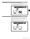
1
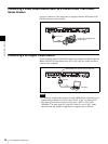
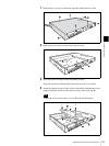
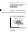
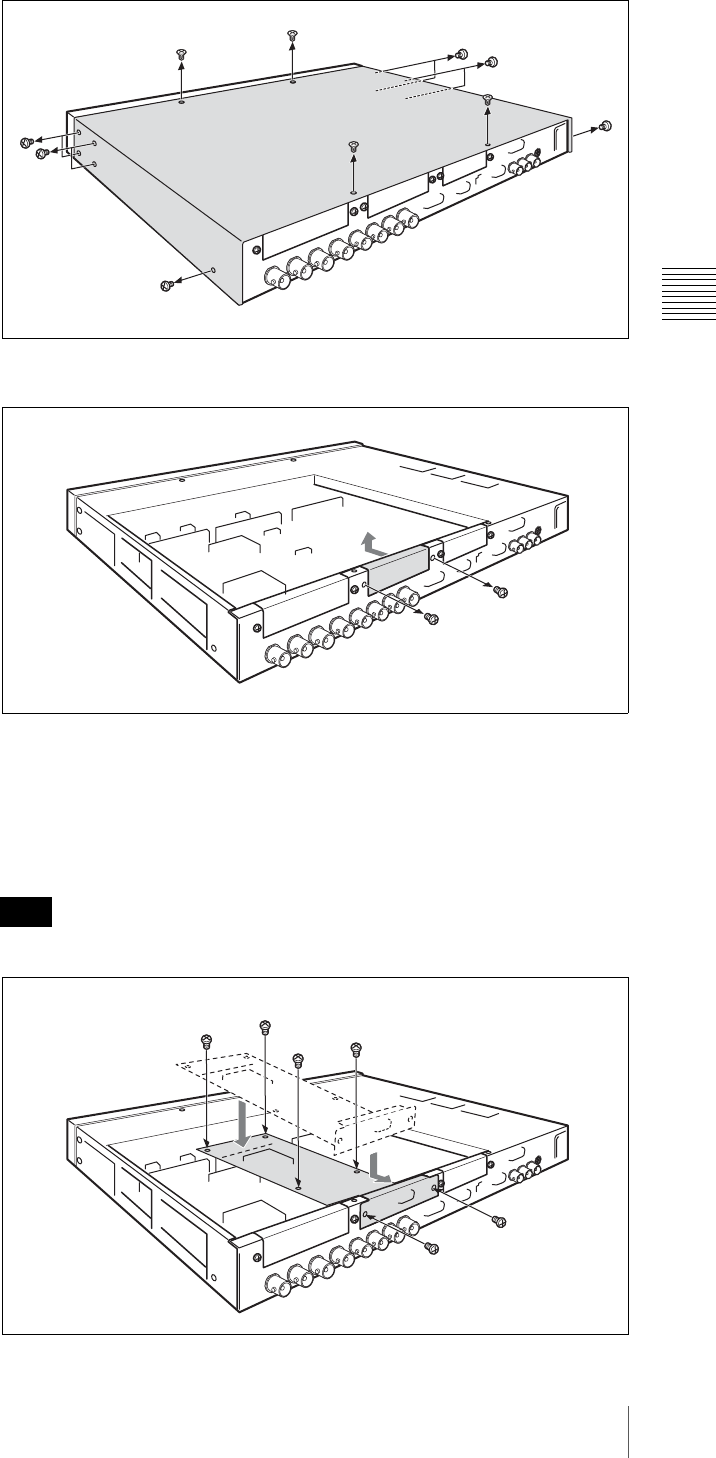
Remove the 14 screws to remove the top panel of the Processor Unit.
2
Remove the two screws to remove the card slot cover.
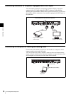
3
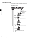
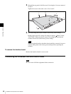
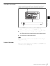
Insert the interface board into the attachment position.
Align the connectors and insert the board securely as far as it will go.
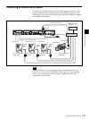
4
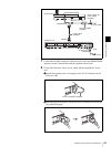
Attach the interface board to the card slot using the four attachment screws
supplied with the interface board and two screws removed in step 2.
Tighten the screws in the order a to f, as shown in the illustration.
Note
e
f
d
a
b
c