


43
Installation and Connection of the Switcher
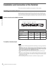
Chapter 3 Preparations
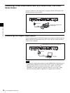
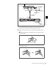
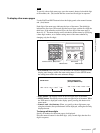
1
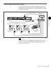
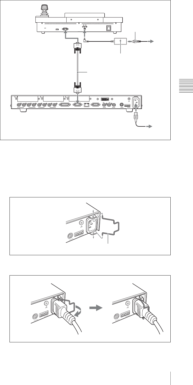
Connect the PANEL connector on the Processor Unit to the PROCESSOR
connector on the Control Panel with the supplied control cable.
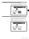
2
Connect the Processor Unit to an AC outlet with the supplied AC power
cord.
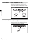
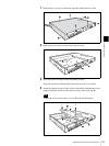
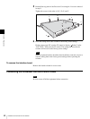
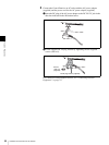
1Attach the supplied power cord stopper to the AC IN connector on the
Processor Unit.
2Insert the plug of the power cord into the AC IN connector and secure the
plug with the stopper.
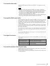
1234PGM1 PGM2 AUX1
SDI OUTSDI IN
AUX2 REF IN REF OUT
RS-232C
~
AC IN
RS-422
DVI-I OUT
GENLOCK VISCA
GPI I/O PANEL LAN(10/100) REMOTE
DC IN 12V
OFF
ON
PROCESSOR
IN1 IN2 OUT
Control Panel
PROCESSOR
Control cable
(supplied)
DC IN 12V
AC power adaptor
(supplied)
Power cord for AC
power adaptor
(supplied)
to an AC outlet
Processor Unit
PANEL
AC power cord
(supplied)
~ AC IN
to an AC outlet
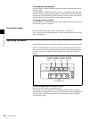
RS-232C
~
AC IN
R
S
-
4
2
2
V
IS
C
A
Power cord stopper (supplied)
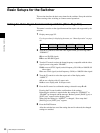
RS-232C
~
AC IN
R
S
-
4
2
2
VISCA
RS-232C
~
AC IN
R
S
-
4
2
2
VISCA