


56
Basic Setups for the Switcher
Chapter 3 Preparations
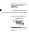
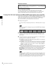
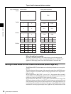
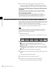
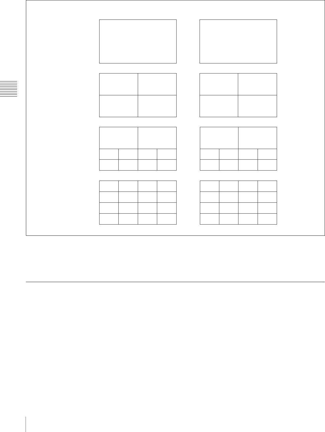
Type of multi-viewer and picture number
When the setting is complete
Press the CAM mode button or SW mode button to exit the menu mode.
If you change the setting, “Save setup data? [PAGE] (yes) or [EXIT] (no)”
appears on the display panel. Press the PAGE button to store the data.
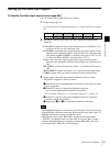
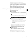
Setting the Bus Mode for the Cross-Point Buttons (Menu Page 943)
The PGM and NEXT select buttons are collectively referred to as cross-point
buttons.
The select button of the program video currently output from the PGM output
connector lights in red, and the button of the program video to be output next
lights in orange.
In bus toggle mode (“BUS TGL” is set to “On.”), the program video currently
output is shown as the PGM select button lit in red, and the program video to be
output next is shown as the NEXT select button lit in orange.
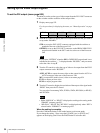
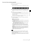
In bus fixed mode (“BUS TGL” is set to “Off.”), the functions of a string of the
PGM select buttons and that of the NEXT select buttons are replaced with each
other depending on the position of the transition lever. When the transition lever
is in the upper end position, the button of the upper string (PGM select button)
indicates the current program output video (lights in red), and the button of the
TYPE1
TYPE4
TYPE10
TYPE16
1
34
78
2
56
910
12
56
910
13 14
34
78
11 12
15 16
PVW
IN 1 IN 2
IN 5 IN 6
PGM
IN 3 IN 4
IN 7 IN 8
PVW PGM
IN 1 IN 2
IN 5 IN 6
IN 9
FM 1 FM 2
IN 3 IN 4
IN 7 IN 8
MAT2MAT1 CLBR
1
12
43
PGM
PVW PGM
IN 2IN 1
Type of multi-viewer
Picture number
Factory preset output video