


60
Basic Setups for the Switcher
Chapter 3 Preparations
4
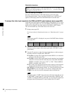
Turn the F3 control to display “ Exec” then press the F3 control.
The selected camera is turned on/off according to the setting in step 3.
Repeating steps 2 to 4 allows the switcher to control each of the cameras.
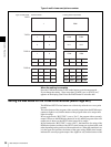
To turn on all the VISCA cameras in conjunction with the power of
the switcher
Turn the F4 control to set “AUTO ON” to “On.” You can turn on all the
connected VISCA cameras automatically when the switcher is turned on.
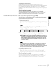
When the setting is complete
Press the CAM mode button or SW mode button to exit menu mode.
If you change the setting, “Save setup data? [PAGE] (yes) or [EXIT] (no)”
appears on the display panel. Press the PAGE button to store the data.
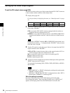
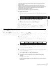
Setting Up the Switcher for Connecting the Computer (Menu Page 963)
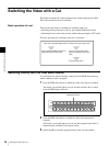
When a computer is connected to the LAN (10/100) connector at the rear of the
switcher with a cross cable, you can store the setting data of the switcher in the
computer, or import the data in the computer to the switcher.
The menu is used to set up the IP address and network mask of the switcher in
order to communicate with the connected computer via FTP.
The IP address of the switcher is 192.168.abc.def and the network mask is
255.255.abc.def. Only the third octet (abc) and the fourth octet (def) are
displayed in the menu and can be changed.
1
Display menu page 963.
For the procedure for displaying the menu, see “Menu Operation” on page
46.
2
Use the F1 control to set up the IP address of the switcher under “IPADD.”
1Press the F1 control to highlight the value of the third octet.
2Turn the F1 control to change the highlighted value. You can enter a
value of 0 to 255.
3Press the F1 control to highlight the value of the fourth octet and change
the highlighted value by turning the F1 control. You can enter a value of
0 to 255.
4Press the F1 control to confirm the values temporarily.
3
Use the F2 control to set up the network mask of the switcher under “NET
MASK.”
Follow the procedure described in step 2.
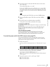
4
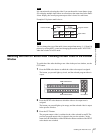
Turn the F3 control to select “Enable” under “FTP.”
5
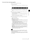
Press the F4 control to confirm the values set in steps 2 to 4.
Pressing the F4 control enables confirmation of the settings.
Note
UTILITY
IPADD NET MASK FTP APPLY 3/3
LAN
1. 1 255. 0 Enable
Exec
963