


Location and Function of Parts and Controls
6(E)
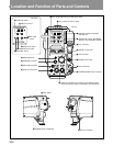
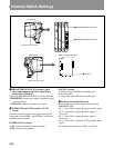
9 DC IN (direct current input) connector (4-pin)
Connects an AC adapter or battery case. Supplies
power to the CA-570/570P when the POWER switch
is set to EXT.
!º PROMPTER/GEN LOCK (prompter signal
input and output/external sync signal input)
connector (BNC type)
Inputs an external sync signal or inputs and outputs a
prompter video signal. Select the respective function
with the PROMPTER/GENLOCK switch on the
internal MD-119 board. The connector is factory set
for PROMPT.
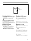
!¡ AUDIO IN 1/AUDIO IN 2 (audio input)
connectors (XLR type, 3-pin) and LINE/MIC
(line input/microphone) switch
Inputs external audio signals. Set the LINE/MIC
switch according to the input signal type.
The following power supply settings can be specified
for the external microphone:
•: +12V is supplied to the external microphone
(when the S800 switch on the AU-251 biard is set
to ON).
OFF: No power is supplied to the external
microphone.
+48V: +48V is supplied to the external microphone.
(when the S700 switch on the AU-251 board is set
to ON).
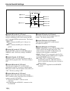
!™ TEST OUT (test video output) connector (BNC
type)
Outputs return video signals, playback video signals,
VBS signal, or monitor output signals. Normally
outputs return video signals when a CCU is connected,
and playback video signals when a VTR is connected.
Note
Select the output signal with switch S100 on the AU-
251 board.
!£ RET CONT (return control) connector (6-pin)
Inputs the control signal for selecting the return video
and for turning the intercom microphone on and off.
!¢ TRACKER connector (10-pin)
Use for communications with a tracker and intercom 1
and 2 communications. Also outputs the up tally and
program audio signals. The maximam output current
output from this connector is 500 mA.
!∞ EARPHONE jack (mini-jack)
Connects an earphone for monitoring the audio from
the VTR, the intercom, or the program. Select the
audio source with the switch S1 on the MB-783 board.
!§ CALL button
Use this button to call the CCU or MSU operator.
When this button is pressed, the red tally lamps in the
viewfinder and on the camera control unit (CCU) or
master setup unit (MSU) light up.
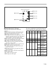
!¶ POWER switch
Selects the power supply.
u CCU: Power is supplied from the CCU.
¬ (standby): Standby mode
1 EXT: Power is supplied from the VTR or EXT DC
IN connector.
!• DC OUT (direct current output) connector (4-
pin)
Outputs a direct current of 10.5 V to 17 V at a
maximum rated current output of 500 mA. Connecting
equipment with a power consumption greater than the
maximum rating will activate the protection circuit,
cutting off the current flow.
!ª PGM (program) level control (for the CA-570P)
Adjusts the audio volume of the program.
@º ENG (engineer) level control (for the CA-570P)
Adjusts the audio volume of the engineer.
@¡ MIC LINE switch (for the CA-570P)
PROD: Selects the producer’s line.
OFF: Turns off the microphone.
ENG: Selects the engineer’s line.
@™ PROD (engineer) level control (for the CA-570P)
Adjusts the audio volume of the producer.
@£ TRACKER (engineer) level control (for the CA-
570P)
Adjusts the audio volume of the tracker.