


9(E)
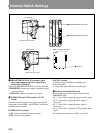
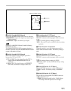
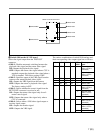
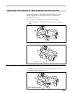
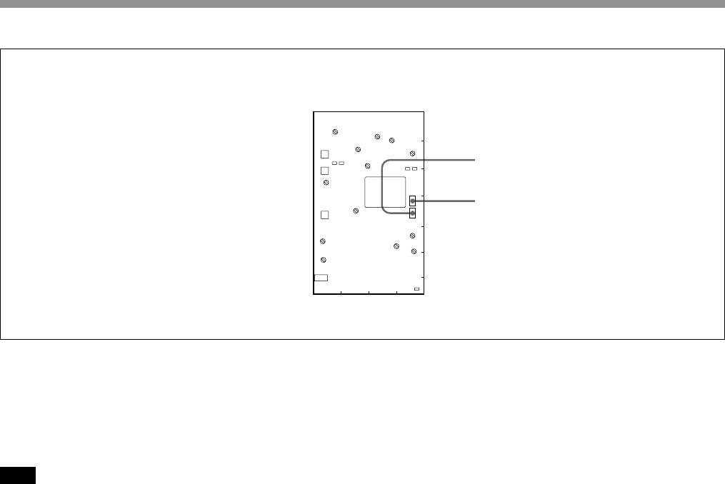
4 Switch S1 on the DM-116 board
Selects the PROMPT/GENLOCK connector function.
PROMPTER: Inputs and outputs a prompter signal
(factory setting).
GENLOCK: Inputs an external sync signal.
Note
Swicth S1 on the DM-116 board is used for factory
inspection use only.
The PROMPTER/GENLOCK connector function is
normally specified using the PROMPTER/GENLOCK
switch on the MD-119 board.
5 Switch S4 on the DM-116 board
Selects the direction of the prompter signal flow
between the CCU and CAM.
CCU→CAM: The video signal from the CCU is
output from the PROMPTER/GEN LOCK
connector.
CAM→CCU: The signal input to the PROMPT/
GEN LOCK connector is output to the CCU.
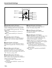
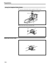
6 S3 switch on the AU-237 board
Specifies whether the incom audio output from
INCOM 2 connector and the program audio are mixed
or not.
IND: No mixing (factory setting for NTSC)
MIX: Mix mode 2 (set by switch S5) (factory setting
for PAL)
7 Switch S4 on the AU-237 board
When this switch is set to ON, the program audio is
mixed with the intercom audio. The factory setting is
OFF.
8 Switch S2 on the AU-237 board
Specifies whether the incom audio output from
INCOM 2 connector and the program audio are mixed
or not.
IND: No mixing (factory setting for NTSC)
MIX: Mix mode 1 (set by switch S4) (factory setting
for PAL)
9 Switch S302 on the AU-237 board
Sets the INCOM 2 connector to either RTS mode or
NORMAL mode. The factory setting is NORMAL
mode.
0 Switch S411 on the AU-237 board
Sets the talk level through the TRACKER connector.
0 dB: Standard level
–20 dB: Decreases the talk level by 20 dB. (Select
this setting when the input level is too high.)
CN2
CN4
E1
FL3
RV2
S1
S4
TP4
CN3
FL1
FL2
LV1
LV2
RV1
TP3
CN5
E2
FL4
LV3
LV4
RV3
RV4
TP5
FL5
A
B
C
D
E
F
G
1234
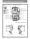
Switch on the DM-116 board
4 Switch S1
5 Switch S4