


8(E)
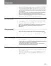
Operation Modes
The CA-702/702P has two operation modes: an output
mode and an input mode. Use the POWER/MODE
switch to select the operation mode.
Output mode (ON/OUT)
• The CA-702/702P outputs the video and audio signal
from the camcorder through the VTR connector or
VIDEO/SDI OUT connector.
• The CA-702/702P outputs the analog component
signal, analog audio signal (CH1), VBS signal, or
SDI signal that is input from the VTR connector. The
output of a VBS signal or SDI signal is automatically
set according to the portable VTR attached to the CA-
702/702P, regardless of the SDI/COMPOSITE switch
setting.
• The SDI output signal can contain up to four channels
of audio.
• Recording operation on the VTR section of the
camcorder and the portable VTR can be synchronized
to the REC START switch on the camcorder.
Synchronization/asynchronization can be specified
through menu operations on the camcorder.
• Set the SDI/COMPOSITE switch to SDI to output an
SDI signal from the VIDEO/SDI OUT connector.
• Pressing the RET button allows you to use the
viewfinder on the camcorder as a monitor for
portable VTR. This function, however, is not
available when using a DNV-5 Recorder Unit.
Notes
• When a portable VTR is connected, the CA-702/702P
outputs signal to the VTR connector. When a
portable VTR is not connected, the CA-702/702P
outputs no signal to the VTR connector.
• A composite signal is not output from the VIDEO/
SDI OUT connector of the CA-702/702P even when
the SDI/COMPOSITE switch is set to COMPOSITE.
To output a composite signal, use the VIDEO OUT
or TEST OUT connector on the camcorder.
• The EARPHONE jack is only for monitoring the
audio from the portable VTR. No signal is output
when the portable VTR is not connected to the CA-
702/702P.
• A VBS signal output to the VTR connector is for
monitoring purposes only, and does not meet the
quality standards for broadcasting.
Input mode (ON/IN)
• In this mode, you can input an external video signal
(composite or SDI) from the VIDEO/SDI IN
connector for recording by the VTR section of the
camcorder. An active-through video signal is output
from the VIDEO/SDI OUT connector at this time.
• Set the SDI/COMPOSITE switch according to the
external video signal type to be input.
• In this mode, you can monitor an externally input
video on the viewfinder of the camcorder, or on a
monitor connected to the VIDEO/SDI OUT or TEST
OUT connector on the camcorder. EXT appears in
the viewfinder during this time.
• When the SDI setting is selected, an audio signal
(CH1, 2, 3, and 4) embedded in the SDI signal is
recorded by the camcorder.
Notes
• The picture may become temporarily unstable to
allow the camcorder to lock to the input signal in the
following cases:
—When an external video signal is input.
—When the operation mode is switched to input
mode.
• During input of an external signal, the composite
signal output from the TEST OUT and VIDEO OUT
connectors of the camcorder is for monitoring
purposes only and does not meet the quality standards
for broadcasting.
• The acceptable frequencies of the input video signals
are limited to the range that the camcorder is able to
lock to. However, if the pulse amplitude modulation
of an input signal falls within broadcasting standards
(NTSC: ±2.8 ppm/PAL: ±1.1 ppm), such a signal is
acceptable.
• An SDI input signal cannot be used to copy an edited
tape.
• The input modes are not available on the DNV-5/
DVW-700/700P/700WS/700WSP.