


5(E)
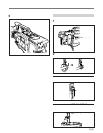
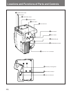
1 INCOM (intercom) LEVEL control
This contorl adjusts the audio volume of the intercom.
2 TALK switch
This switch selects the voice transmission mode to the
camera control unit (CCU).
ON: The cameraperson’s voice is transmitted to the
CCU.
OFF: The cameraperson’s voice is not transmitted to
the CCU.
REMOTE: Transmission of the cameraperson’s
voice to the CCU is turned on or off by a signal
input by the RET CONT connector.
3 PGM (program) LEVEL control
This control adjusts the program audio volume.
4 PROD(producer)/ENG(engineer) switch
Set this switch to the intercom line to be used.
PROD: Producer’s line
ENG: Engineer’s line
5 CALL button
When you press this button, the red tally lamps on the
CCU and in the viewfinder light up. Use this button to
call the CCU operator.
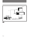
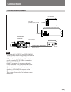
6 Triax connector
Connect a CCU-550/550P/700/700P Camera Control
Unit to this connector.
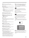
7 RET (return video) 2 button
While this button is pressed, the return video signal 2
from the CCU appears in the viewfinder.
8 RET (return video) 1 button
While this button is pressed, the return video signal 1
from the CCU appears in the viewfinder.
9 EARPHONE jack (minijack)
Connect an 8-ohm earphone to this jack to monitor the
intercom and program sound.
!º INCOM (intercom)/PGM (program)
connector (XLR-type, 5-pin)
Connect a headset to this connector to transmit/receive
over the intercom and monitor the program audio.
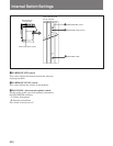
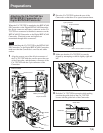
When the microphone you are going to use is a
dynamic microphone, detach the side panel on the CA-
755/755P and set the INCOM MIC switch to D
(dymamic). This switch is factory set to C (carbon).
For details, see “Internal Switch Settings” (next page).
!¡ DC IN 11.5-17.0 V connector (XLR-type, 4-pin)
Connect an AC-550/550CE AC Adapter to this
connector to power the DNW-7/7P/90/90P/90WS/
90WSP or the DVW-700/700P/700WS/700WSP when
a CCU is not connected.
Note
When a CCU is connected and an external power
supply is connected to the DC IN connector, power
supplied from the DC IN connector takes precedence
over other power sources.
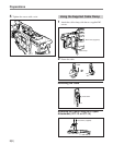
!™ Accessory mounting holes
Attach the supplied cable clamp or other accessories to
this section.
Note
Attaching a WRR-28H/28L/28M UHF Portable Tuner
or WRR-860A UHF Synthesized Diversity Tuner to
the CA-755/755P requires a special mounting kit.
For details, contact Sony Service Personnel.
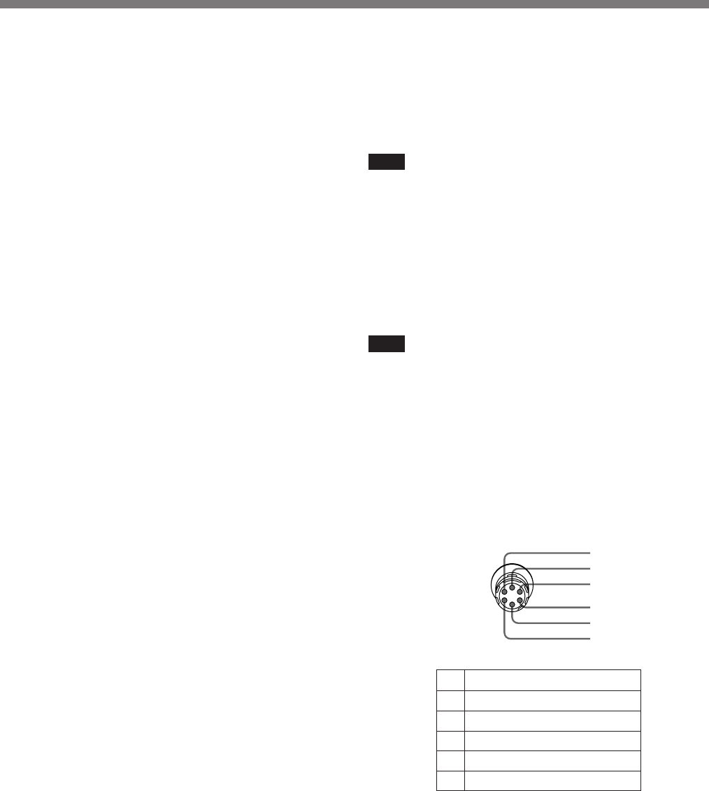
!£ RET CONT (return video control) connector
(6-pin)
This connector inputs the signal for selecting the return
video and for turning the intercom microphone on and
off.
1 INCOM MIC ON/OFF
2NC
3GND
4NC
5 RET 1
6 RET 2
Pin configuration
1
2
3
4
5
6
!¢ RET (return video) OUT connector (BNC-type)
This connector outputs the return video signal.
Normally outputs the return video 1 signal, but outputs
the return video 2 signal while the RET 2 button is
pressed.