


Location and Function of Parts
14
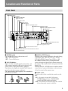
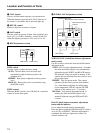
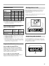
4 OUTPUT switch
Use this switch to select the type of the signal to be
output from the R/R-Y, G/Y, B/B-Y connectors or the
S VIDEO connector.
R/G/B: The R, G, and B color signals are output
from the R/R-Y, G/Y, and B/B-Y connectors,
respectively. No signal is output from the S
VIDEO connector at this time.
R-Y.Y.B-Y: The R-Y, Y, and B-Y component
signals are output from the R/R-Y, G/Y, and B/B-
Y connectors, respectively. No signal is output
from the S VIDEO connector at this time.
S VIDEO: The S-video signal is output from the S
VIDEO connector. No signals are output from the
R/R-Y, G/Y, and B/B-Y connectors at this time.
5 R/R-Y, G/Y, and B/B-Y (component video
signal/RGB signal output) connectors (BNC type)
Use these connectors to output the signals from the
video camera as RGB color signals or component
signals (R-Y, B-Y, and Y).
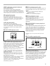
6 MIC OUT (microphone output) connector (XLR
3-pin)
Use this connector to output microphone signal from
the connected video camera.
7 CAMERA connector (Z-type 26-pin)
Connect a camera cable here to connect this unit to the
CA-537/537P Camera Adaptor attached to a video
camera.
8 AC IN connector
Use this connector to connect an AC power source via
the supplied power cord.
9 REMOTE (remote control unit) connector (10-
pin)
Use this connector to connect the RM-M7G Remote
Control Unit using a CCA-7 connecting cable (not
supplied).
q; INTERCOM/TALLY terminals (screw
terminals)
Use these terminals to connect an intercom system
which cannot be connected to qa TALLY/
INTERCOM connector (DIN 4-pin).
qa TALLY/INTERCOM connector (DIN 4-pin)
Intercom signals and tally signals are input and output
via this connector. Connect to the intercom system’s
INTERCOM/TALLY connector using a CCDD-2.5
tally/intercom cable (not supplied).
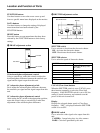
qs S VIDEO (S-video signal output) connector
(mini DIN 4-pin)
Use this connector to output S-video signal from the
video camera.
qd SYNC OUT (sync signal output) connector
(BNC-type)
This connector outputs the sync signal from the video
camera.
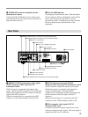
qf MONITOR OUT (picture monitor output)
connector (BNC-type)
Use this connector to output the composite video
signal to a video monitor. When the MENU button on
the front panel of this unit is pressed, information on
the settings made in the AUX operations section of this
unit can be added to the output signal.
qg RETURN VIDEO (return video signal) IN/OUT
connectors (BNC type) and 75Ω termination switch
The IN connector accepts the on-the-air signal or
signal currently being recorded from a control console
or a special effects generator, and the OUT connector
supplies the same signal to the viewfinder of the
camera. The IN and OUT connectors are loop-through
connectors, with the signal input from the IN
connector being directly output to the OUT connector.
When no external device is connected to the OUT
connector, the 75Ω termination switch should be set to
ON.
Notes
• When the return video signal is input from the
RETURN VIDEO IN connector, be sure to input the
sync signal from the GENLOCK IN connector.
• The signal input from the RETURN VIDEO IN
connector must be synchronized with the signal input
from the GENLOCK IN connector. Otherwise,
camera synchronization may be unstable.