


24
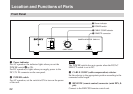
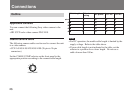
Location and Functions of Parts
3 WE. OUT (Write Enable pulse output) connector
(BNC type)
Outputs the WE pulse to communicate the timing to store
the image on an external frame memory, etc.
For detailed information, read the instruction manual of the
DXC-H10.
4 TRIG IN (trigger input) connector (BNC type)
Inputs the trigger pulse. You can control the electronic
shutter by using the trigger pulse input to this connector.
For detailed information, read the instruction manual of the
DXC-H10.
5 HD (horizontal deflection) input/output connector
(BNC type)
Inputs or outputs the HD signal. Input or output can be
selected by setting the IN/OUT selector 7.
6 VD/SYNC (vertical deflection/sync) input/output
connector (BNC type)
Inputs or outputs the vertical deflection signal, tri-level sync
signal or bi-level sync signal. Input or output can be selected
by setting the IN/OUT selector 7.
The type of sync signal is set on the PAGE 3/3 menu of the
video camera.
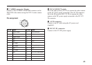
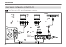
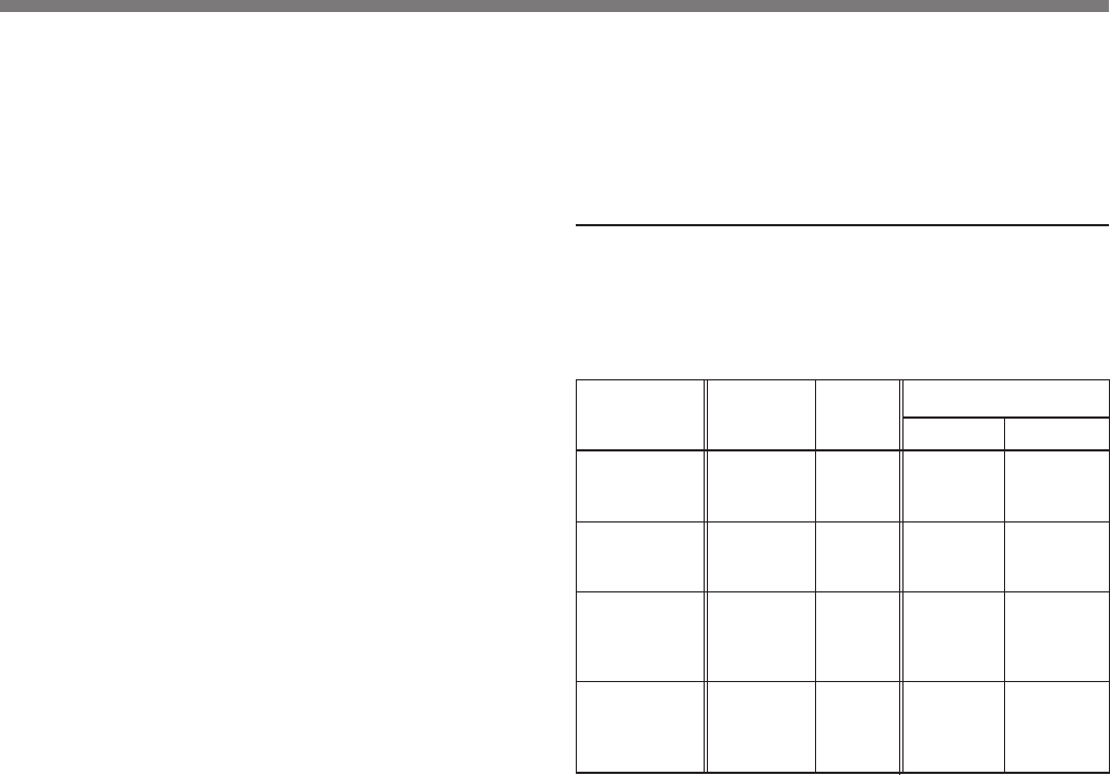
Using the HD and VD/SYNC connectors
The following table shows how to use the HD and VD/
SYNC connectors combined with the menu setting on the
video camera and the IN/OUT selector on this unit.
7 IN/OUT (sync input/output) selector
Set to IN to use the HD connector 5 and VD/SYNC
connector 6 as inputs, and to OUT to use them as outputs.
It should be set to OUT when external sync is not used.
Purpose
To use HD and
VD signals for
external sync
To use SYNC
signal for
external sync
To use HD and
VD signals
output from the
camera
To use SYNC
signal output
from the
camera
Function of connector
HD
HD signal
input
Not used
HD signal
output
HD signal
output
VD/SYNC
VD signal
input
SYNC
signal input
VD signal
output
SYNC
signal
output
Menu
setting on
camera
Any
Any
Set SYNC/
VD to VD on
PAGE 3/3
menu
Set SYNC/
VD to SYNC
on PAGE 3/
3 menu
IN/OUT
selector
setting
IN
IN
OUT
OUT