


20
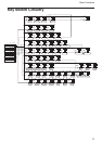
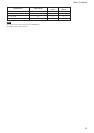
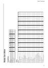
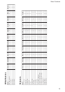
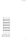
Command List
................................................................................................................................................................................................................................
1)VISCA is a protocol which controls consumer camcorders developed by Sony. “VISCA” is a trademark of Sony Corporation.
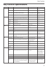
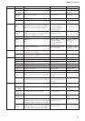
Command List
VISCA
1)
/RS-232C
Commands
This Manual outlines an RS-232C control protocol and
command list for certain Sony cameras from which
control software can be developed.
THIS CONTROL PROTOCOL AND COMMAND
LIST IS PROVIDED BY SONY ON AN “AS-IS
BASIS” WITHOUT WARRANTY OF ANY KIND.
SONY DOES NOT WARRANT ANY PARTICULAR
RESULT FROM THE USE OF THIS CONTROL
PROTOCOL AND COMMAND LIST AND
DISCLAIMS AND EXCLUDES ALL
WARRANTIES, EXPRESS OR IMPLIED, WITH
RESPECT TO THAT CONTROL PROTOCOL AND
COMMAND LIST, INCLUDING, BUT NOT
LIMITED TO, ANY OR ALL IMPLIED
WARRANTIES OF MERCHANTABILITY OR
FITNESS FOR A PARTICULAR PURPOSE. IN
FACT, SONY SPECIFICALLY ACKNOWLEDGES
THAT SOFTWARE DEVELOPED BASED ON THIS
CONTROL PROTOCOL AND COMMAND LIST
MAY CAUSE MALFUNCTION OR DAMAGE TO
HARDWARE AND SOFTWARE USED WITH IT
(INCLUDING SONY HARDWARE AND
SOFTWARE) AND SPECIFICALLY DISCLAIMS
ANY LIABILITY FOR ANY SUCH
MALFUNCTION OR DAMAGE. THIS CONTROL
PROTOCOL AND COMMAND LIST SHOULD BE
USED WITH CAUTION.
Overview of VISCA
In VISCA the device outputting commands, for
example, a computer, is called the controller. The
device receiving the commands, an FCB series camera
is called the peripheral device. In this case, an FCB
series camera, is itself one of the peripheral devices.
In VISCA, up to seven peripheral devices like the FCB
series camera can be connected to one controller using
communication conforming to the RS-232C standard.
The parameters of RS-232C are as follows:
• Communication speed: 9.6 kbps/19.2 kbps/
38.4 kbps
• Data bits : 8
• Start bit : 1
• Stop bit : 1/2
• Non parity
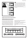
Peripheral devices are connected in a daisy chain. As
shown in the following figure, the actual internal
connection is a one-direction ring, so that messages
return to the controller via the peripheral devices. The
devices on the network are assigned addresses.
The address of the controller is fixed at 0. The
addresses of the peripheral devices are 1, 2, 3 ... in
order, starting from the one nearest the conttoller. The
address of the peripheral device is set by sending
address commands during the initialization of the
network.