


21
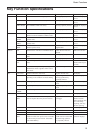
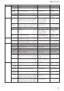
Command List
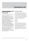
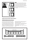
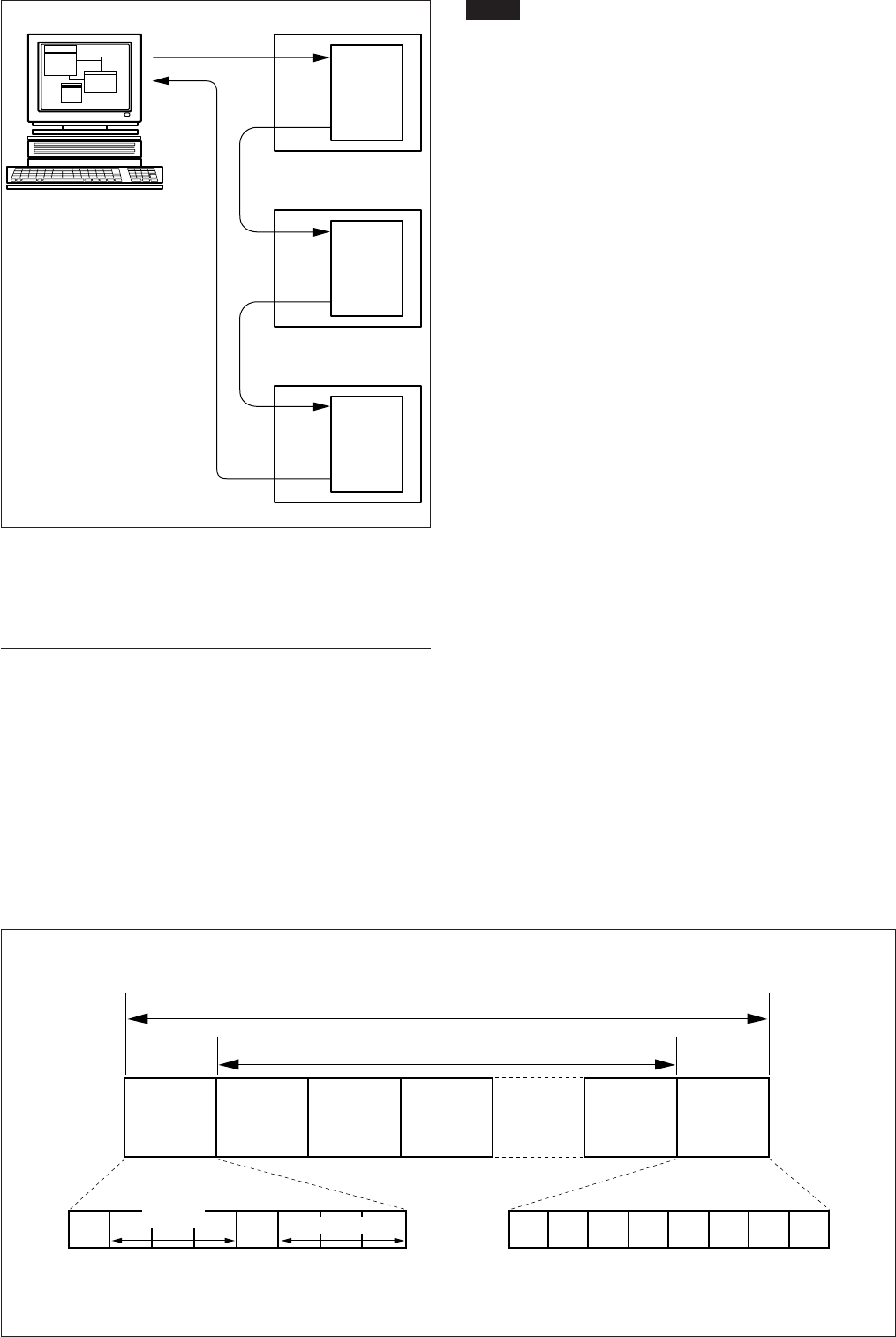
VISCA network structure
Notes
•Connect the serial output from the PC to the serial
input of camera 1, then connect the serial output of
camera 1 to the serial input of camera 2, the serial
output of camera 2 to the serial input of camera 3,
and the serial output of camera 3 to the serial input of
the PC. (Up to seven cameras may be connected.)
• Power on all the units connected in series.
•Mixed existence of RS-232C and TTL signal levels is
not allowed.
VISCA Communication Specifications
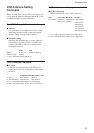
VISCA Packet Structure
The basic unit of VISCA communication is called a
packet. The first byte of the packet is called the header
and comprises the sender’s and receiver’s addresses.
For example, the header of the packet sent to the FCB
series camera assigned address 1 from the controller
(address 0) is hexadecimal 81H. The packet sent to the
FCB series camera assigned address 2 is 82H. In the
command list, as the header is 8X, input the address of
the FCB series camera at X. The header of the reply
packet from the FCB series camera assigned address 1
is 90H. The packet from the FCB series camera
assigned address 2 is A0H.
Some of the commands for setting FCB series cameras
can be sent to all devices at one time (broadcast). In
the case of broadcast, the header should be
hexadecimal 88H.
When the terminator is FFH, it signifies the end of the
packet.
Bit 7
(MSB)
Bit 6 Bit 5 Bit 4 Bit 3 Bit 2 Bit 1 Bit 0
(LSB)
10
FF
Bit 7
(MSB)
Bit 6 Bit 5 Bit 4 Bit 3 Bit 2 Bit 1 Bit 0
(LSB)
11111111
Packet (3 to 16 bytes)
Message (1 to 14 bytes)
Header
Byte 1 Byte 2 Byte 3
Sender’s
address
Receiver’s address
Terminator
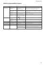
VISCA Equipment
RXD
TXD
RXD
TXD
RXD
TXD
VISCA Controller
RXD
TXD
Camera 1
Camera 2
Camera 3