


3-20 (E)
HDCU-900 MM
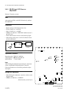
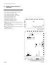
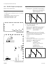
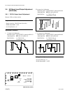
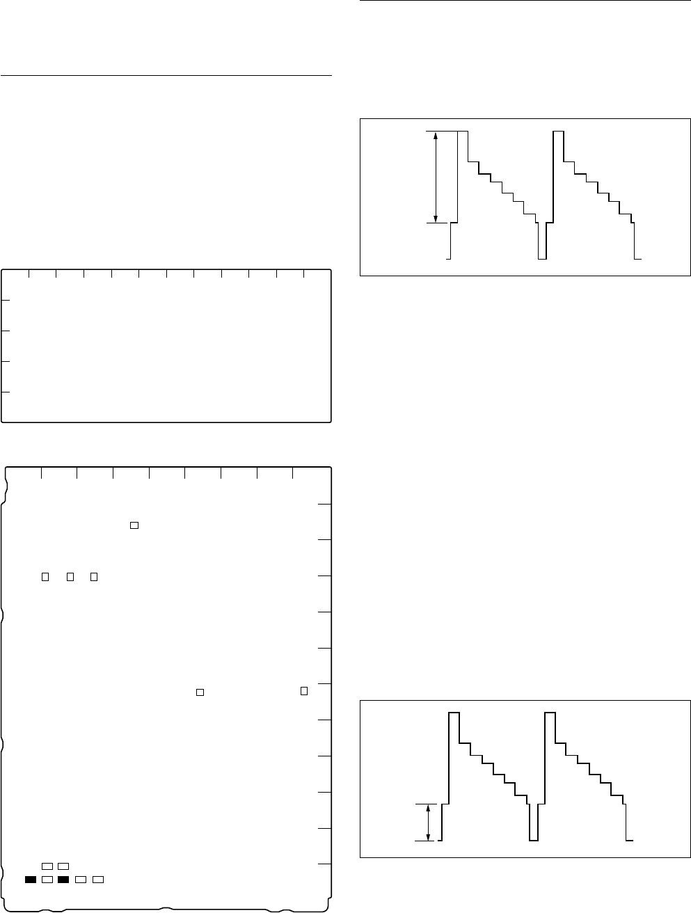
3-5-5. Y/R-Y/B-Y Output Level Adjustment
Measure : SD waveform monitor
Preparation
. The GRB output level adjustment (section 3-5-4) should
be completed.
. Board extension : VDA-57 board (rear side)
. S705 (M-8)/IF-789A/789P → YCD
. S201 (M-8)/IF-789A/789P → OFF
Adjustment Procedure
1. Measuring point : Y/G OUTPUT connector/VDA-57
Measure level A. (about 100 IRE or
700 mV (terminated at 75 Z))
(100% (Y) color bar)
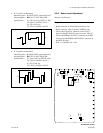
2. S201 (M-8)/IF-789A/789P → ON
3. Y signal level adjustment
Measuring point : Y/G OUTPUT conenctor/VDA-57
Adjusting point : 1RV211 (C-7)/IF-789A/789P
Specifications : B = A (terminated at 75 Z)
(100% color bar)
n
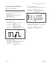
When turning ON S201 (M-8) on the IF-789A/789P
(with SET UP added) and turning off (when SET UP is
not added), the level of A and B should not be
changed.
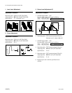
4. SYNC level adjustment
Measuring point : Y/G OUTPUT connector/VDA-57
Adjusting point : 1RV63 (F-2)/VDA-57
Specifications : C = 40 ±2 IRE
(terminated at 75 Z)
(100% (Y) color bar) (for UC)
C = 300 ±14 mV
(terminated at 75 Z)
(100% (Y) color bar) (for CE)
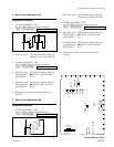
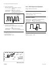
IF-789A/789P board (A side)
VDA-57 board (A side)
C
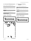
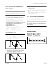
3-5. SD Signal System Adjustment (HKCU-901)
A, B
ABCDEFGHJKLM
1
2
3
4
5
RV63
RV61
1
1
RV62
1
RV65
1
RV66
1
RV64
1
RV124
1
RV121
1
A
B
C
D
E
F
G
H
J
K
L
M
123456789
S706
S708
S101
S705
S202
S201
S707
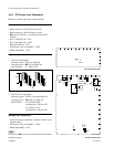
11 1
RV214
RV216
RV215
TP206
TP205
TP207
111
RV204
RV203
RV202
RV209
1
1
RV207
1
RV211
RV213
1
RV212
1
RV208
1
TP202
111
11
RV501
RV503
RV502
RV405
RV406
1
RV402
1
RV205
1
RV210
1
RV217
TP503
TP405
1
RV401
1
RV404