


3-5 (E)
HDCU-900 MM
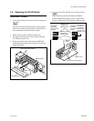
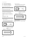
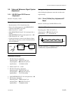
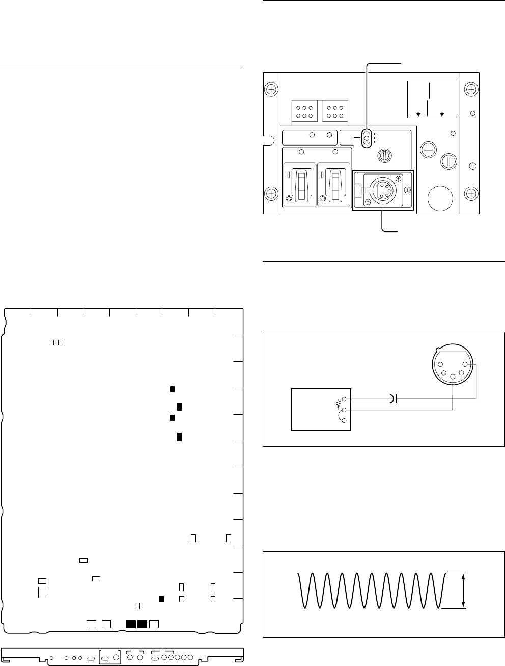
3-2-2. Front Intercom Microphone Level
Adjustment
Measures : Oscilloscope, Audio generator
Note
This adjustment is described on the premise that the output
impedance of the audio oscillator is 600 Z.
DYNAMIC
OFF
CARBON
INTERCOM
CAMERA
MIC
POWERPOWER
MAIN
CAMERA
MAIN
RED TALLY
GREEN TALLY
CABLE
ALARM
SHORT
OPEN
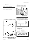
MIC switch
INTERCOM connector
S404
TP405
TP502
TP402
TP613TP608
TP401
S504
S603
S126S602
S601
RV501
RV502
RV506
RV505
RV405
S503
TP503
TP504
S41 S403
S128
1
1
11
1
1
1
A
B
C
D
E
F
G
H
J
K
L
M
123456789
AT
POWER
/1.001
FINE
HD BB
REMOTE LOCAL
REFERENCE H PHASE
MIC LEVEL
REF
IN
GEN
LOCK
NORM
MIN MIN
12
ENG PROD
PRIVATE
NORM
INCOM
SELECT
TALK
LEVEL
PGM
MIX
SIDE
TONE
2 WIRE
CANCEL
CH-1 CH-2
CCU
S401
S402
RV402
1
RV604
1
RV603
1
RV605
1
RV602
RV401
S102
S110
S101
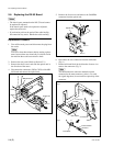
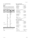
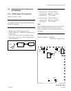
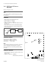
AT-141 board (A side and panel side)
Preparation
. MIC switch/HDCU front panel → CARBON
. Board extension : AT-141 board (front side)
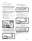
Adjustment Procedure
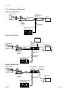
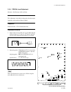
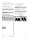
1. Connect the audio oscillator and the INTERCOM
connector on the HDCU front panel as shown in the
following figure.
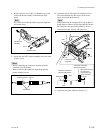
2. Input a sine wave of 1 kHZ, 220 mV p-p (_20 dBu)
from the audio oscillator.
3. Measuring point : TP503 (M-4)/AT-141
Adjusting point : 1RV506 (TALK LEVEL)/AT-141
board panel side
Specifications : A = 200 ±10 mV p-p
220 uF
(16 V or more)
600 Z
GND
1
2
3
4
5
+
Audio generator
A
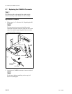
3-2. Audio System Adjustment