2 (E)
HDCU-900 MM
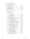
2. Replacement of Main Parts
2-1. Replacing the Switching Regulator.......................................................2-1 (E)
2-2. Replacing the Fuse ................................................................................2-2 (E)
2-3. Removing the Rear Panel ......................................................................2-3 (E)
2-4. Replacing the DC Fan (Rear Panel) ......................................................2-3 (E)
2-5. Replacing the PS-587 Board .................................................................2-5 (E)
2-6. Replacing the RX-53 Board ..................................................................2-6 (E)
2-7. Replacing the CAMERA Connector .....................................................2-8 (E)
3. Electrical Alignment
3-1. Preparation ............................................................................................3-1 (E)
3-1-1. Required Equipment.............................................................3-1 (E)
3-1-2. Notes on Adjustments ..........................................................3-1 (E)
3-1-3. Connection of Equipment ....................................................3-2 (E)
3-1-4. Initialization Settings ...........................................................3-3 (E)
3-2. Audio System Adjustment ....................................................................3-4 (E)
3-2-1. Microphone Level Adjustment ............................................3-4 (E)
3-2-2. Front Intercom Microphone Level Adjustment ...................3-5 (E)
3-2-3. RTS Intercom Adjustment ...................................................3-6 (E)
3-2-4. PGM Mix Level Adjustment ................................................3-7 (E)
3-2-5. Side Tone Level Adjustment ................................................3-8 (E)
3-3. Video and Reference Signal System Adjustment .................................3-9 (E)
3-3-1. HD-SDI Output VCO Free-run Adjustment ........................3-9 (E)
3-3-2. Clock (74 MHz) Duty Adjustment/AT Board .....................3-9 (E)
3-3-3. Clock (74 MHz) Duty Adjustment/DPR Board .................3-10 (E)
3-3-4. Prompter Level Adjustment ...............................................3-10 (E)
3-4. Video Signal System Adjustment (RC-86 Board) ..............................3-11 (E)
3-4-1. SD-SDI Output VCO Adjustment ......................................3-11 (E)
3-4-2. SD-SDI Input VCO Free-run Adjustment..........................3-12 (E)
3-4-3. Main Clock (74 MHz) Duty Adjustment ...........................3-13 (E)
3-4-4. Return Clock (74 MHz) Duty Adjustment .........................3-13 (E)
3-4-5. PIX Output Level Adjustment ...........................................3-14 (E)
3-4-6. WF Output Level Adjustment ............................................3-15 (E)
3-4-7. STAIR CASE Adjustment .................................................3-15 (E)
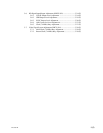
3-5. SD Signal System Adjustment (HKCU-901)......................................3-16 (E)
3-5-1. VBS Output Level Adjustment ..........................................3-17 (E)
3-5-2. PIX Output Level Adjustment ...........................................3-17 (E)
3-5-3. WF Output Level Adjustment ............................................3-18 (E)
3-5-4. GRB Output Level Adjustment ..........................................3-19 (E)
3-5-5. Y/R-Y/B-Y Output Level Adjustment ...............................3-20 (E)
3-5-6. Return Level Adjustment ...................................................3-21 (E)


