


3-17 (E)
HDCU-900 MM
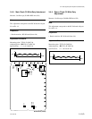
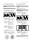
3-5-1. VBS Output Level Adjustment
Measures : SD waveform monitor, Vector monitor
Preparation
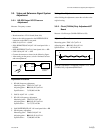
Board extension : VDA-57 board (rear side)
Adjustment Procedure
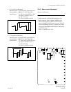
1. SYNC level adjustment
Measuring point : TP202 (B-6)/IF-789A/789P
Adjusting point : 1RV209 (C-6)/IF-789A/789P
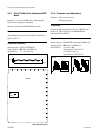
Specifications : A = 571 ±3 mV (for UC)
A = 600 ±3 mV (for CE)
2. Video level adjustment
Measuring point : TP202 (B-6)/IF-789A/789P
Adjusting point : 1RV202 (D-6)/IF-789A/789P
Specifications : B = 1429 ±5 mV (for UC)
B = 1400 ±5 mV (for CE)
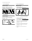
3. VBS1 OUT level adjustment
Measuring point : VBS OUT1 connector/VDA-57
Adjusting point : 1RV62 (L-5)/VDA-57
Specifications : C = 100.0 ±0.5 IRE
(terminated at 75 Z) (for UC)
C = 700.0 ±3.5 mV
(terminated at 75 Z) (for CE)
4. VBS2 OUT level adjustment
Measuring point : VBS OUT2 connector/VDA-57
Adjusting point : 1RV61 (M-4)/VDA-57
Specifications : D = 100.0 ±0.5 IRE
(terminated at 75 Z) (for UC)
D = 700.0 ±3.5 mV
(terminated at 75 Z) (for CE)
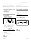
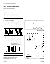
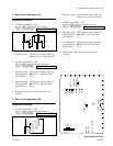
5. Chroma adjustment
Adjust the PHASE knob of the vector monitor so that
75% of the luminescent spot of the burst is aligned
with the axis.
Measuring point : VBS OUT1 connector/VDA-57
Adjusting point : 1RV208 (C-7)/IF-789A/789P
Specifications : The luminescent spot should be
located inside “4”.
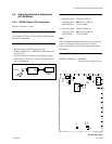
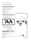
3-5-2. PIX Output Level Adjustment
Measure : SD waveform monitor
Preparation
. The VBS output level adjustment (section 3-5-2) should
be completed.
. PIX monitor select switch/MSU → ENC
. Board extension : VDA-57 board (rear side)
Adjustment Procedure
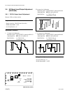
1. PIX signal level adjustment
Measuring point : PIX OUT connector/VDA-57
Adjusting point : 1RV121 (F-5)/VDA-57
Specifications : A = 100.0 ±0.5 IRE
(terminated at 75 Z) (for UC)
A = 700 ±3.5 mV
(terminated at 75 Z) (for CE)
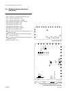
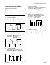
2. PIX monitor select switch/MSU → R, G or B
3. SYNC level adjustment
Measuring point: PIX OUT connector/VDA-57
Adjusting point: 1RV207 (C-6)/IF-789A/789P
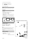
Specifications: B = 40.0 ±0.5 IRE
(terminated at 75 Z) (for UC)
B = 300.0 ±3.5 mV
(terminated at 75 Z) (for CE)
4. Video level adjustment
Measuring point : PIX OUT connector/VDA-57
Adjusting point : 1RV204 (D-6)/IF-789A/789P
Specifications : C = 75.0 ±0.5 IRE
(terminated at 75 Z) (for UC)
C = 525.0 ±3.5 mV
(terminated at 75 Z) (for CE)
Setting after Adjustment
PIX monitor select switch/MSU → ENC
[for CE]
[for UC]
B,
C,
D
B,
C,
D
A A
R
M
G
B
C
Y
G
Y
L
R
M
G
C
Y
G
Y
L
B
[for UC] [for CE]
[for CE]
[for UC]
A
A
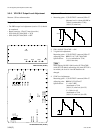
3-5. SD Signal System Adjustment (HKCU-901)
C
B