


3-21 (E)
HDCU-900 MM
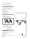
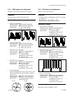
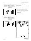
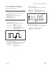
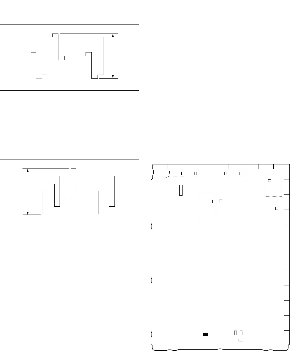
5. R-Y signal level adjustment
Measuring point :
R-Y/R OUTPUT connector/VDA-57
Adjusting point : 1RV213 (C-7)/IF-789A/789P
Specifications :
D = 700 ±5 mV p-p (SET UP : ON)
(75% (R-Y) color bar) (for UC)
D = 525 ±5 mV p-p
(75% (R-Y) color bar) (for CE)
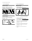
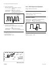
6. B-Y signal level adjustment
Measuring point :
B-Y/B OUTPUT connector/VDA-57
Adjusting point : 1RV212 (C-8)/IF-789A/789P
Specifications :
E = 700 ±5 mV p-p (SET UP : ON)
(75% (B-Y) color bar) (for UC)
E = 525 ±5 mV p-p
(75% (B-Y) color bar) (for CE)
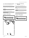
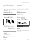
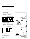
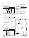
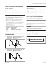
3-5-6. Return Level Adjustment
Measure : Oscilloscope
Preparation
. Board extension: IF-789A/789P board (front side)
. Board extension: VDA-55 board (CAMERA side)
. Connect the VBS OUT1 connector on the VDA-57
board and the RET INPUT1 connector on the VDA-57.
. Connect the SERIAL OUTPUT1 connector on the DIF-
102 board and the SERIAL RET INPUT1 connector on
the DIF-102 board.
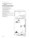
. S811-1, 2 (M-6)/RC-86 → ON
D
E
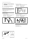
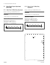
RC-86 board (A side)
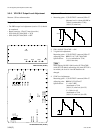
3-5. SD Signal System Adjustment (HKCU-901)
A
B
C
D
E
F
G
H
J
K
L
M
123456789
S803
RV351
RV354
S801
S802
S811
11
RV353
RV350
RV352
11
1
TP603
TP352
1
RV601
COR601
TP350
TP351
1
TP501
RV501
1
TP502
RV502
COR501
TP201
RV201
TP703
RV701
Suffix:14_
Suffix:14_
1
1