


3-23 (E)
HDCU-900 MM
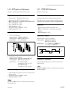
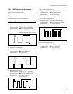
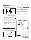
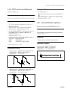
4. Return Level Adjustment (Pr)
Adjustment Procedure
1. CONFIG button/MSU → ON
Set using MSU on the touch panel as follows.
[
CCU] → [RET|SETTING] →
RET1 : 2nd Slot (DIF-RET-1)
2. Measuring point : TP31/extension board (VDA-55)
Measure level F. (about 1050 mV)
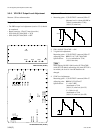
3. CONFIG button/MSU → ON
Set using MSU on the touch panel as follows.
[CCU] → [RET|SETTING] →
RET1 : 3rd Slot (VDA-RET-1)
4. Measuring point : TP31/extension board (VDA-55)
Adjusting point : 1RV405 (G-1)/IF-789A/789P
Specifications : G = F
5. Measuring point : TP31/extension board (VDA-55)
Adjusting point: 1RV503 (G-1)/IF-789A/789P
Specifications : H = 0
6. Repeat steps 4 and 5 until the specifications are
satisfied.
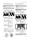
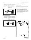
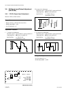
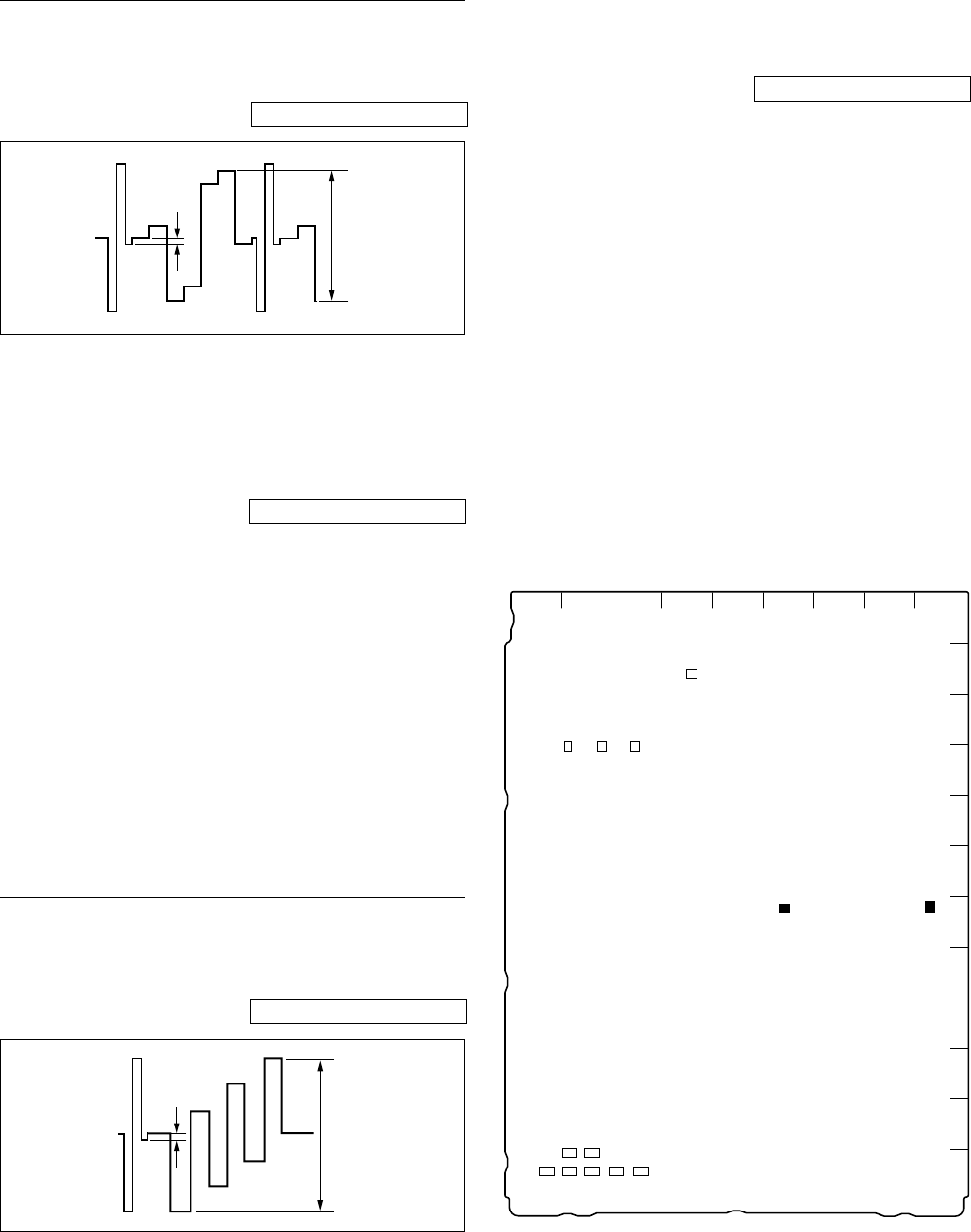
5. Return Level Adjustment (Pb)
Adjustment Procedure
1. CONFIG button/MSU → ON
Set using MSU on the touch panel as follows.
[CCU] → [RET|SETTING] →
RET1 : 2nd Slot (DIF-RET-1)
2. Measuring point : TP43/extension board (VDA-55)
Measure level J. (about 1050 mV)
3. CONFIG button/MSU → ON
Set using MSU on the touch panel as follows.
[CCU] → [RET|SETTING] →
RET1 : 3rd Slot (VDA-RET-1)
4. Measuring point : TP43/extension board (VDA-55)
Adjusting point : 1RV406 (G-1)/IF-789A/789P
Specifications : K = J
5. Measuring point : TP43/extension board (VDA-55)
Adjusting point : 1RV502 (G-1)/IF-789A/789P
Specifications : L = 0
6. Repeat steps 4 and 5 until the specifications are
satisfied.
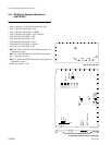
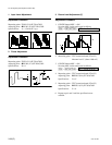
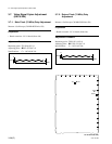
IF-789A/789P board (A side)
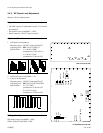
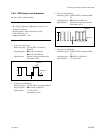
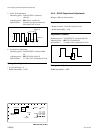
3-5. SD Signal System Adjustment (HKCU-901)
H
F, G
J, K
L
A
B
C
D
E
F
G
H
J
K
L
M
123456789
S706
S708
S101
S705
S202
S201
S707
1 1 1
RV214
RV216
RV215
TP206
TP205
TP207
111
RV204
RV203
RV202
RV209
1
RV207
1
RV211
1
RV208
1
TP202
111
11
RV501
RV503
RV502
RV405
RV406
1
RV402
1
RV205
1
RV210
1
RV217
TP503
TP405
1
RV401
1
RV404