


1-21 (E)
HDCU-900 MM
Page 4
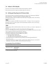
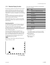
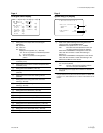
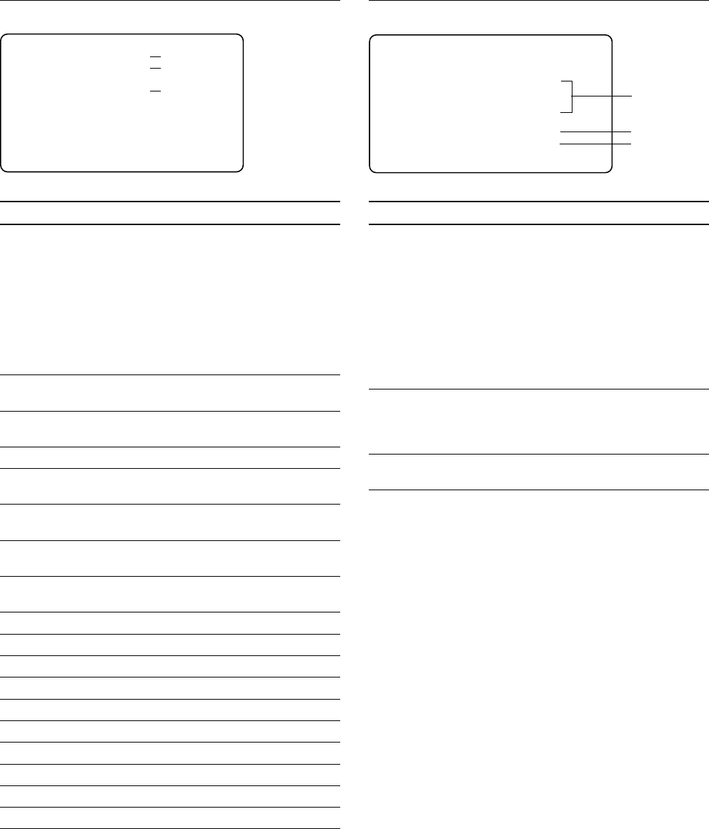
SD Signal Status Display
No. Contents
1 Setting state of the aspect ratio of the SD signal
(SQ/LB/EC)
SQ : Squeeze
LB : Letter box
EC : Edge crop
Displays the crop position too. (_99 to 99)
_99 :The cut-out position is in the leftmost position.
0 : Cuts out the center.
99 : The cut-out position is in the rightmost
position.
2 Setting state of the H down-converter interpolation filter
coefficient (A to E)
3 Setting state of the V down-converter interpolation filter
coefficient (A to E)
4 Setting state of SD GAMMA (_99 to 99)
5 Setting state of the linear matrix correction coefficient
(ON/OFF)
6 Setting state of the cross-color reducing function
(ON/OFF)
7 Setting state of the coring level of the cross-color
reducing (_99 to 99)
8 Setting state of the reducing level of the cross-color
reducing (_99 to 99)
9 Setting state of the detail function (ON/OFF)
0 Setting state of the detail level (_99 to 99)
!- Setting state of the detail limiter (_99 to 99)
!= Setting state of the detail crispening (_99 to 99)
![ Setting state of the level dependent knee (_99 to 99)
!] Setting state of the detail H/V ratio (_99 to 99)
!\ Setting state of the detail boost frequency (_99 to 99)
!; Setting state of the detail white limiter (_99 to 99)
!' Setting state of the detail black limiter (_99 to 99)
!, Setting state of the level dependent gain (_99 to 99)
Page 5
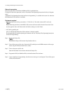
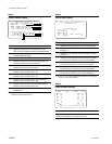
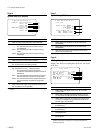
System Diag (1/3) Display
No. Contents
1 State of the optical receiving level of the camera and
camera control unit (OK/WARNING/NG)
*3
WARNING :The optical level is _17 to _20 dBm.
NG : The state when the optical level is low and
any signal waveform cannot be obtained
When either of WARNING or NG appears on the CCU
side, clean the connector or cable while referring to
Section 1-7.
When either of WARNING or NG appears on the camera
side, clean the connector or cable while referring to the
Maintenances Manual of the camera.
2 State of the fan of the power supply block and the fan of
the rear panel (OK/NG)
NG : The fan of the switching regulator and the
fan of the rear panel are defective.
3 Accumulated power supply time to the AT-141 board is
displayed.
*3 : The optical sending/receiving state of the main unit also can be checked
using the indicator on the panel of the DPR-163 board. For details, refer
to Section 1-4-2, “DPR-163 Board” of “Functions of the Indicators on the
Boards”.
EC: 0 H:A V:A : 0
SD Matrix OFF
CC Reduce OFF
COR 0 LEV 0
SD Detail OFF
Level 0 Lim-w 0
Limit 0 Lim-b 0
Crisp 0 LDgain 0
LDKnee 0
Ratio 0
Freq 0
γ
1
7
0
!-
!=
![
!]
!\
23
5
6
9
4
8
!;
!'
!,
* System Diag 1/3 *
Optical Condition
Camera OK
CCU OK
Fan Power OK
Timer 117H
2
3
1
1-12. Character Display Function