


3-6 (E)
HDCU-900 MM
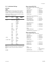
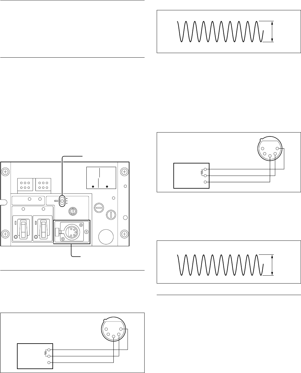
3-2-3. RTS Intercom Adjustment
Measures : Oscilloscope, Audio generator
Note
. This adjustment is described on the premise that the
output impedance of the audio oscillator is 600 Z.
. When the intercom system is the RTS system, perform
this adjustment.
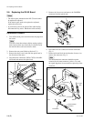
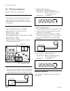
Preparation
. MIC switch/HDCU front panel → CARBON
. Board extension : AT-141 board (front side)
. S504 (J-2)/AT-141 → RTS
. S404 (J-1)/AT-141 → RTS
.
S503 (INCOM SELECT)/AT-141 board panel side → PROD
. S41 (L-3)/AT-141 → RTS
. S403 (L-2)/AT-141 → RTS
. Connect a resistance of 200 Z between A74-pin and
A75-pin of the extension board.
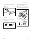
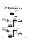
Adjustment Procedure
1.
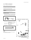
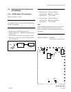
Input a sine wave of 1 kHz, 220 mV p-p (_20 dBu) from
the audio oscillator to 2-pin (X), 1-pin (Y) and 3-pin (G)
of the INTERCOM connector on the HDCU front panel.
2. PROD CANCEL adjustment
Measuring point : TP502 (M-3)/AT-141
Adjusting point : 1RV505 (2WIRE CANCEL 1)/
AT-141 board panel side
Specifications : A = Minimize
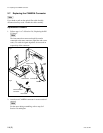
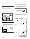
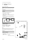
3. ENG CANCEL adjustment
S503 (INCOM SELECT)/AT-141 board panel side → ENG
4. Connect a resistance of 200 Z between A72-pin and
A73-pin of the extension board.
5. Input a sine wave of 1 kHz, 220 mV p-p (_20 dBu)
from the audio oscillator to 2-pin (X), 1-pin (Y) and 3-
pin (G) of the INTERCOM connector on the HDCU
front panel.
6. Measuring point : TP405 (M-2)/AT-141
Adjusting point : 1RV405 (2WIRE CANCEL 2)/
AT-141 board panel side
Specifications : B = Minimize
Setting after Adjustment
After adjustment is completed, return the switches to the
original setting.
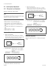
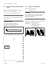
DYNAMIC
OFF
CARBON
INTERCOM
CAMERA
MIC
POWERPOWER
MAIN
CAMERA
MAIN
RED TALLY
GREEN TALLY
CABLE
ALARM
SHORT
OPEN
MIC switch
INTERCOM connector
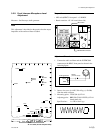
3-2. Audio System Adjustment
600 Z
GND
1
2
3
4
5
Audio oscillator
A
600 Z
GND
1
2
3
4
5
Audio oscillator
B