


3-25 (E)
HDCU-900 MM
3-6. HD Signal Input/Output Adjustment (HKCU-902)
3-6-2. GBR Output Level Adjustment
Measure : HD waveform monitor
Preparation
. The Y/P
B
/P
R
output level adjustment (section 3-6-1)
should be completed.
. Board extension : ADA-59 board (rear side)
. S1 (F-2)/ADA-59 → 8
. BARS button/MSU → ON
Adjustment Procedure
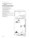
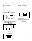
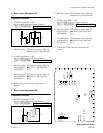
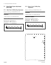
1. G mix level adjustment
Measuring point : Y/G OUTPUT1 connector/
ADA-59
Adjusting point : 1RV102 (J-4)/ADA-59
1RV103 (J-4)/ADA-59
Specifications : Portion A and portion B must be
flat (within 5 mV).
2. G signal level adjustment
Measuring point : Y/G OUTPUT1 connector/ADA-59
Adjusting point : 1RV104 (K-4)/ADA-59
Specifications : C = 700 ±5 mV
(terminated at 75 Z)
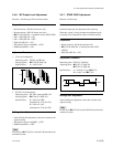
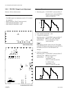
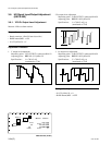
3. B mix level adjustment
Measuring point : P
B
/B OUTPUT1 connector/ADA-
59
Adjusting point : 1RV202 (K-4)/ADA-59
Specifications : Portion D and portion E must be
flat (within 5 mV).
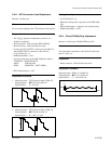
4. B signal level adjustment
Measuring point : P
B
/B OUTPUT1 connector/ADA-
59
Adjusting point : 1RV203 (L-4)/ADA-59
Specifications : F = 700 ±5 mV
F
Portion D
Portion E
C
Portion A
Portion B