


3-27 (E)
HDCU-900 MM
3-6. HD Signal Input/Output Adjustment (HKCU-902)
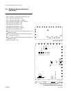
3-6-4. A/D Conversion Level Adjustment
Measure : Oscilloscope
Note
Do not connect anything to the VTR connector of the camera.
Preparation
. The Y/P
B
/P
R
output level adjustment (section 3-6-1)
should be completed.
. Board extension : VDA-55 board (HDC-900/950)
. Board extension : ADA-59 board (rear side)
. Connect the Y/G OUTPUT1 connector on the ADA-59
and the RET INPUT1 connector on the ADA-59.
. S1 (F-2)/ADA-59 → C
. BARS button/MSU → ON
. Set on the setup menu of the HDC-900/950 as follows.
TOP MENU : MAINTENANCE
PAGE : VTR-26P (M9)
ITEM : VIDEO SEL → RET (YPbPr)
. RET1 button/camera → ON
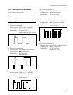
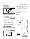
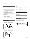
Adjustment Procedure
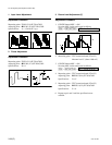
1. Measuring point : TP37/extension board (VDA-55)
Adjusting point : 1RV501 (B-3)/ADA-59
Specifications : A = 0 ±5 mV
2. Measuring point : TP37/extension board (VDA-55)
Adjusting point : 1RV502 (B-4)/ADA-59
Specifications : B = 1400 ±1 0 mV
A
Setting after Adjustment
. S1 (F-2)/ADA-59 → 0
. Return the setting on the setup menu of the HDC-900/
950.
. RET1 button/camera → Return to the original setting.
. BARS button/MSU → OFF
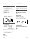
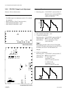
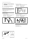
3-6-5. Clock (74 MHz) Duty Adjustment
Measure : Oscilloscope (20 MHz BWLimit: ON)
Note
This adjustment corresponds to the ADA-59 board with
part No. suffix -14.
Preparation
. Board extension : ADA-59 board (rear side)
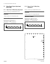
Adjustment Procedure
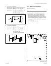
Measuring point : TP601 (C-3)/ADA-59
Adjusting point : 1RV1 (E-3)/ADA-59
Specifications : C = 1.65 ±0.04 Vdc
B
A
B
A=B
C
GND